1 Introduction
Calibration refers to adjusting, optimizing and determining the control parameters of each ECU (such as engine, AT and other subsystem ECUs) on the vehicle according to various vehicle performance requirements (such as power, economy, emissions and auxiliary functions) Control algorithm. The calibration system is mainly composed of the upper computer and the bottom ECU. Therefore, the communication method between the upper computer and the bottom ECU plays a vital role in the performance of the entire calibration system. At present, the general calibration system adopts the point-to-point communication method based on the serial port. This communication method is easy to realize, but there are defects such as slower communication speed and lower reliability. Here we use the communication method of CAN bus. Compared with serial communication, the communication method based on CAN bus has the advantages of reliable communication [1], fast transmission speed, and online programming.
2 Overall design
CAN communication can be regarded as an I / O character stream device of the system [3], while it completes the ordinary sending and receiving functions, it must also realize the device independence necessary for the driver. That is, the driver should encapsulate all the hardware features of the system to provide a hardware-independent and universal programming interface for the application program that uses the device. Application layer programmers can successfully control the device without understanding the principle of the device , Through this device to achieve reliable data exchange. In addition, for the real-time requirements of CAN communication and embedded systems, the driver requires reliable data transmission and reception code, short delay, short system time, short interrupt execution time, short shutdown interrupt time, and when receiving and sending errors and abnormal conditions To report to the application. In addition, the driver needs to monitor the working status of the CAN controller, reset the CAN module when a fatal error occurs and leave the bus, and report to the system.
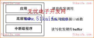
Figure 1 The overall structure of the driver
Based on the above needs analysis, combined with the drive scheme of other I / O serial devices implemented in other OS and the characteristics of CAN bus requirements, the overall driver structure is designed as shown in Figure 1.
3 Realization of CAN drive module
Based on the above overall design framework, first define a CAN class to encapsulate the data structures and functions in CAN communication. The bottom layer is an interrupt level program. The interrupt handler wakes up the driver program every time the CAN controller completes sending and receiving. Work in one step. In the interrupt processing program, it is determined according to different interrupt vectors whether the transmission completion interrupt or the acceptance completion interrupt currently occurs, and complete the corresponding work. The middle layer is the bottom layer driver program. The bottom layer driver program mainly completes the configuration and status detection of the CAN port by reading and writing the CAN controller registers, and provides interfaces for device-independent software and user programs. In this layer, a ring buffer structure must be established. The buffer consists of a receive ring buffer and a send ring buffer. Its data structure is shown in the following code. For each ring buffer, design A storage pointer points to the next storage address to be stored in CANMsg, a read pointer points to the address of the next (oldest) CANMsg to be taken out of the buffer, and a counter records how many CANMsg are waiting in the current buffer Take out, a semaphore, used to exchange messages with the application. The receive ring buffer is used to buffer the received bus messages, waiting for application processing, and the send ring buffer is used to buffer the messages sent by the application, waiting for processing by the sending interrupt program.
typedef struct {// Data structure of ring buffer
INT16U RingBufRxCtr; // Receive counter
OS_EVENT * RingBufRxSem; // Semaphore
CAN_msg * RingBufRxInPtr; // The storage pointer of the receiving buffer
CAN_msg * RingBufRxOutPtr; // Read pointer of receive buffer
CAN_msg RingBufRx [CAN_RX_BUF_SIZE]; // Receive buffer message storage
INT16U RingBufTxCtr; // Send counter
OS_EVENT * RingBufTxSem;
CAN_msg * RingBufTxInPtr; // Save pointer in send buffer
CAN_msg * RingBufTxOutPtr; // Read pointer of send buffer
CAN_msg RingBufTx [CAN_TX_BUF_SIZE]; // Message storage of send buffer
} CAN_RING_BUF;
3.1 Low-level driver
The underlying driver module provides our application with interface functions for receiving and sending messages.
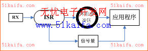
Figure 2 CAN receive message
When receiving a message [3], as shown in Figure 2, the application waits at the semaphore; after receiving a message, the ISR reads the message from the serial port and stores it in the ring buffer. The ISR then sends a semaphore to notify the task waiting for serial data that a message has been received. After waiting for the task to receive the semaphore, it enters the ready state and is ready to be activated by the OS scheduler. When the kernel schedules the task to run, the task takes the message from the ring buffer and completes the process of receiving the message.
void CAN_GetMsg (CAN_msg * msg) {
INT8U oserr;
OS_CPU_SR cpu_sr;
CAN_RING_BUF * pbuf;
pbuf = & ringbuf;
OSSemPend (pbuf-> RingBufRxSem, 0, & oserr); // Wait for semaphore
OS_ENTER_CRITICAL (); // Off interrupt
pbuf-> RingBufRxCtr-; // Reception counter decrements by 1
CopyMsg (pbuf-> RingBufRxOutPtr ++, msg); // Remove the semaphore from the ring buffer
if (pbuf-> RingBufRxOutPtr == & pbuf-> RingBufRx [CAN_RX_BUF_SIZE]) {pbuf-> RingBufRxOutPtr = & pbuf-> RingBufRx [0];
// If the read pointer of the ring buffer reaches the end of the buffer, change it to point to the first address of the buffer}
OS_EXIT_CRITICAL (); // Open interrupt, allow CPU to respond to interrupt}
Sending CAN messages is similar to receiving messages. The background process stores the message frame to be sent in the sending ring buffer. When the CAN port is ready to send a frame of message, an interrupt is generated, the CAN message is taken from the buffer and output by the ISR [4]. But there is a problem: the CAN port can only generate an interrupt when the last data is sent. The time when the interrupt is generated is inconsistent with the time we need to perform the interrupt task. The way to solve this problem is to disable the sending end interrupt enable until the message needs to be sent again. When the system is started, it is forbidden to send an interrupt and send a start message frame. At this time, the send complete interrupt flag has been set, but because the send interrupt enable bit is low, no interrupt can occur and the system continues to execute. When the first message needs to be sent, put the message into the send ring buffer, and then run the send interrupt. At this time, the last send message completed interrupt is generated and the message is sent. At the end of sending a message, if there is other data in the sending ring buffer that needs to be sent, clear the interrupt source and wait for the completion of the message to send an interrupt to send the next message. If there is no other data to be sent, the sending is directly prohibited Interrupt, the interrupt generated when the message is sent is reserved until the next time a message needs to be sent.
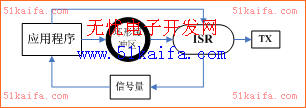
Figure 3 CAN sending message
The method of sending messages is shown in Figure 3. When the sending ring buffer is full, the semaphore is used as an indicator to suspend the sending task. When sending a message, the task waits for the semaphore. If the ring buffer is not full, the task continues to store the message to be sent to the ring buffer. If the stored message is the first byte of the buffer, the interrupt is allowed to be sent and the interrupt program is ready to start. CAN sends the ISR to take the oldest message from the ring buffer, and at the same time sends the semaphore to notify the sending task, indicating that the ring buffer has room to receive another message, and then the ISR sends the message from the bus. The implementation code is as follows:
void CAN_PutMsg (CAN_msg * msg) {
INT8U oserr;
OS_CPU_SR cpu_sr;
CAN_RING_BUF * pbuf;
pbuf = & ringbuf;
OSSemPend (pbuf-> RingBufTxSem, 0, & oserr); // Wait for semaphore
OS_ENTER_CRITICAL (); // Off interrupt
pbuf-> RingBufTxCtr ++; // Increment the sending counter by 1
CopyMsg (msg, pbuf-> RingBufTxInPtr ++); // Put the message into the ring buffer
if (pbuf-> RingBufTxInPtr == & pbuf-> RingBufTx [CAN_TX_BUF_SIZE]) {pbuf-> RingBufTxInPtr = & pbuf-> RingBufTx [0];
}
if (pbuf-> RingBufTxCtr == 1) {
CAN_TxIntEn (); // It is the first message of the ring buffer, open to send interrupt
}
OS_EXIT_CRITICAL ();
}
3.2 Interrupt service routine
According to the software structure of sending and receiving messages mentioned earlier, the CAN receiving interrupt is required to be turned on when CAN is initialized, and the sending interrupt is only turned on after the first message is in the sending buffer, so in Two interface functions are designed here, CAN.TxIntEn () and CAN.TxIntDis (), which will send the transmission mask position 1 (allow transmission completion interrupt) and set to 0 (disable transmission completion interrupt).
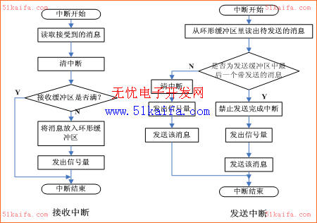
Figure 4 Send and receive interrupt program flow chart
The core of the interrupt level program is CANRX_ISR () and CANTX_ISR (), which are set by the interrupt setting register of the module's interrupt setting register during initialization. As shown in Figure 4, if the interrupt is received, the source of the interrupt is cleared, the received message is placed in the receive buffer; the message is stored in the receive buffer, the pointer points to the address, and the pointer is moved down , The receive buffer counter is increased by 1 and a semaphore is sent to notify the application that a new message has been received. If a task is waiting for a new message on CAN, the task enters the ready state and waits for OS scheduling. If the transmission is interrupted, the message to be sent in the send buffer is read out; the oldest message (the message pointed to by the buffer fetch pointer) is read from the one with the highest priority and the message to be sent, and the send buffer counter Decrease by 1, send a semaphore to inform the application that a message has been sent, and report the status of the current send buffer; it should also determine whether it is the last message to be sent, if not, then clear the interrupt source and send the message to the bus If it is the last one, it is forbidden to send the message after sending the completion interrupt, and the transmission completion interrupt is reserved and allowed to be generated when the application program next sends the message.
3.3 Application
The application of the driver is shown in the following code. Here, uCOS-II is used. First, define a CAN message object (msg) and a ring buffer data structure (CANRingBuf). In the main program, call Ringbuf_Init after initializing the OS The () function initializes the ring buffer area, and then calls the CAN_Init () function to initialize the CAN port. After starting the OS, users can call CAN_PutMsg (CAN_msg * msg) and CAN_GetMsg (CAN_msg * msg) in any task to send and receive bus messages.
CAN_msg msg;
CAN_RING_BUF CANRingBuf;
void main (void) {
OSInit ();
Ringbuf_Init ();
CAN_Init ();
/ * Creat task1 * /
OSStart ();}
void task1 (void * data)
{CAN_PutMsg (& msg);
CAN_GettMsg (& msg);
}
4 Conclusion
By repeatedly debugging the chip bus frequency and CAN communication rate for many times, this CAN driver runs stably and reliably on the real-time operating system without data loss, and the communication between the host computer and the ECU is better achieved. Therefore, it has a very good Strong practical value.
LED Wall Clock
This Clock with LED wall light is a fancy choice for wall decorations in any public places or home decor.
It's working by light sensor with built in LED on the clock hand, driven by either D type battery or electricity.
When in the dark, the clock hand will light up automatically, which you'll read time easily even in the night, while in the daytime, when light sensor receiving light, the LED light will be automatically off.
We have size from 14 inch to 16 inch with material from metal, glass, mirror and wood, surely be a fancy wall decorations with lights for your home, suitable to match with lighting fixtures, easy for wall hanging, stable lighting quality.
Lighting Clock,Light Clock,Light Up Clock,Black Mirror Wall Clock
Guangzhou Huanyu Clocking Technologies Co., Ltd. , https://www.findclock.com