1 Introduction
The energy and environmental crisis brought about by the rapid development of modern transportation has become a worldwide problem. The development of electric vehicles and the use of clean energy are considered to be one of the best solutions. To this end, countries have invested a lot of manpower and material resources to conduct research on electric vehicles, and achieved gratifying results.
Electric vehicles include not only parameters such as the operating speed and mileage of traditional vehicles, but also electrical parameters such as energy consumption, power supply voltage, current, and motor speed that are unique to electric vehicles, with more than 100 parameters. Mastering these parameters is of great significance for analyzing the overall operating performance of electric vehicles. These parameters are of different types and scattered in position, so it is very difficult to concentrate on measurement. Therefore, it is necessary to decentralize the measurement, and then construct the test network by means of centralized display and recording of the monitoring nodes. The controller area network CAN (controller area network) can effectively support serial communication of distributed and real-time control. Compared with other field buses, it has many advantages such as simple and reliable, high speed, no master-slave and convenient connection, etc. The bus form of mature application in the vehicle vehicle measurement and control network. Therefore, we choose CAN bus to construct a test network of electric vehicle parameters.
2. The overall structure of the CAN bus network
2.1 Overall structure of the monitoring network

Figure 1 Block diagram of the overall structure of the system
The electric vehicle vehicle operating parameter monitoring network is composed of 9 CAN nodes, including a PC104 monitoring node responsible for network scheduling and data processing and 8 single-chip data acquisition nodes. The 8 data collection nodes include 1 vehicle parameter collection node, 1 power battery parameter collection node, 1 auxiliary battery parameter collection node, 1 motor parameter collection node and 4 battery parameter collection nodes. Since the parameters collected by the power battery node, auxiliary battery node, and motor node are voltage, current, and charge and discharge energy, these three nodes can be designed as a type of node, collectively referred to as the power parameter collection node. The power battery is composed of 40 12V lead-acid batteries connected in series. The performance of the series battery depends on the performance of each battery. The parameters of the 40 batteries are measured in 4 battery nodes. Each node is responsible for testing the parameters of 10 batteries. Therefore, the 4 battery parameter collection nodes are another type of data collection nodes. In addition, there is a vehicle parameter collection node, which mainly collects various states of the vehicle, including vehicle start and stop, air conditioner switch status, engine speed (for hybrid vehicles), motor speed. Therefore, this system includes three types of data collection nodes, namely power nodes, battery nodes and vehicle nodes. The structure of the entire system is shown in Figure 1.
In the whole system, there are 3 types of 8 data collection nodes, which complete the collection of 146 parameters. The collected data is sent to the monitoring node through the CAN bus, and the monitoring node also receives the data on the bus through the microprocessor. At the same time, the node communicates with the ISA bus of a PC104 computer through the dual-port RAM. PC104 obtains the data received from the bus by the monitoring node through the dual-port RAM, and displays and records the data. At the same time, PC104 also directly receives the vehicle speed, latitude and longitude and clock information of the GPS data receiving board through a serial port, and records and displays it as synchronization information, so as to connect the real-time performance of the car with the speed and running conditions. The information is recorded every 0.5 seconds, using the data compression algorithm of the change record and stored in the * .dat file format.
2.2 Information transmitted in the network
The CAN bus transmits data through information frames, which can be divided into data frames, remote frames, error frames, and overload frames. Information is transmitted in message units. Different messages are distinguished by identifiers (ID). The smaller the identifier, the higher the priority of the message.

The message identifier sent by the monitoring node is 00H, which is used to send query information to the data collection node. After receiving the query information from the monitoring node, the collection node sends its own packet of data to the bus. The monitoring node confirms this after receiving it. The node is working properly. In this way, the monitoring node can query the data collection nodes connected to the network at any time. Since the data length carried in the message is a maximum of 8 bytes, it is necessary to allocate more message identifiers to the power nodes and battery nodes with more measurement parameters. Each battery node is assigned 2 identifiers, and each battery is assigned 1 identifier. Because the message identifier associated with the parameter is fixed, it is possible to determine which parameter was received based on the received identifier. The corresponding relationship between the message identifier (ID) and parameters transmitted in the electric vehicle parameter monitoring network is shown in Table 1:
Table 1 Message identifier and parameter correspondence table 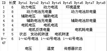
3. Design of data acquisition node
As an operation parameter monitoring network, data collection is the basis of the system. The system has 8 data acquisition nodes in 3 categories, namely vehicle parameter acquisition nodes, 3 power parameter acquisition nodes and 4 battery parameter acquisition nodes. The following will introduce the design of the three types of nodes.
All data acquisition nodes in the system use the structure shown in Figure 2, including a microprocessor, a CAN controller and a CAN transceiver. The microprocessor uses INTEL's 80C196KB, which is mainly responsible for collecting the parameters of the outside world, and at the same time managing and scheduling the work of the node. When a reasonable set of data is collected, the CAN controller is used to send data to the bus. The CAN controller selects SJA1000, which integrates the bus protocol of CAN2.0A and CAN2.0B, and is responsible for sending and receiving data. The CAN transceiver 82C250 is the interface between the CAN controller and the physical bus. Its internal drive circuit has a current limiting circuit, which provides differential transmission and reception of the bus. At the same time, it uses photoelectric isolation to exchange data with the bus, which helps to suppress cars. Transient interference in harsh electrical environments.
3.1 Design of vehicle parameter acquisition node
The parameters collected by the vehicle node include vehicle start and stop states, air conditioner switch status, motor and engine speed information. From the point of view of the characteristics of the collected parameters, they are divided into switching and frequency quantities. For the acquisition of the switching quantity, no additional sensor is needed, and only the voltage signal needs to be directly input into the input port of the microprocessor through photoelectric coupling to detect; for the rotational speed of the frequency quantity, we have selected a Hall sensor for measurement. A magnetic steel sheet is attached to the output shaft. When the magnetic steel sheet passes through the Hall element, the Hall sensor outputs a pulse. This pulse is input to the high-speed input port of 80C196 through photoelectric isolation. Since the high-speed input port can automatically record the time of pulse jump , Can accurately measure the pulse, and both high and low frequencies are applicable. The block diagram of the vehicle collection node is shown in Figure 3.
3.2 Design of power node
For electrical parameters such as voltage and current, the usual A / D conversion is easy to measure; but for electrical energy parameters, because it is the time-integrated value of voltage and current, it is difficult to measure using ordinary methods. Therefore, for the electricity measurement, the integrated electricity measurement chip CS5460A is selected, which can measure the voltage, current, power and energy of both at the same time. CS5460A is a single-phase bidirectional power / energy measurement integrated circuit chip with a serial SPI interface, which is mainly used in single-phase electronic energy meters and three-phase electronic energy meters. After the chip completes a calibration, the calibration coefficients are stored in the EEPROM of the system. Each time the power is turned on, the CPU reads the calibration coefficients from the EEPROM and writes them to the measurement chip, and then writes commands through the SPI interface to perform the corresponding current and voltage. And electrical energy measurement. Through the SPI interface, the microprocessor reads the measurement results in the chip, updates the energy information in the EEPROM, and sends it to the CAN bus by way of a message.

In order to ensure the reliable operation of the measuring circuit, the measuring circuit is designed to isolate the SPI interface of the CS5460A and the I / O port of the microprocessor through the photoelectric isolation device to prevent mutual interference. Because the data line (SDI, SDO) and clock line (SCLK) signals of the SPI interface of the chip change rapidly, the high-speed optocoupler 6N137 is used for isolation, and the coupling rate can reach 10Mbps; while the chip selects (CS) and reset (RESET) And the interrupt (INT) output signal is a level signal, and the conversion rate is very low, which can be achieved with a common photocoupler TLP521-1.
3.3 Battery parameter collection node design
Electric vehicle power batteries are made up of 40 12V lead-acid batteries connected in series. The performance of each battery will affect the performance of the entire battery pack. Therefore, it is necessary to measure the parameters of each battery. Including the voltage and current of each battery and the status of the measurement sensor. Since there are 40 batteries in total, the measurement task with one node is too large. Therefore, 4 nodes are designed to measure 40 batteries. Each node is responsible for the measurement of 10 battery parameters. The battery parameters are only voltage and current. The A / D conversion is obtained, so the design of the battery node will not be described in detail.
4. Design of monitoring node based on PC104
Because the 146 parameters of the entire network test must be displayed and recorded, the single-chip microcomputer system with the microprocessor as the core is obviously unable to meet such heavy task requirements. In addition, the development of single-chip microcomputer will inevitably bring huge workload. In order to provide users with a friendly human-computer interaction interface and reduce the development workload, the monitoring node selects an embedded PC104 module with a compact structure and similar hardware and software functions to the PC for development.
The PC104 module uses an embedded CPU, selects a 256MB pocket Flash disk as the system hard drive, stores the operating system, application programs, and collects data, and selects a Sharp 10.4-inch LCD screen as the interface for man-machine exchange.
The interface mode of PC and peripherals is flexible and diverse, which determines that the interface mode of CAN controller and PC is also various. Common methods are: RS-232 serial port, parallel printing port, USB interface, ISA bus interface, etc. In this system, PC104 obtains the data of the intelligent receiving node through dual-port RAM communication. The so-called intelligent receiving node refers to the node equipped with a microprocessor, which completes the data exchange with the PC104 through the dual-port RAM, sends the data received from the bus to the PC104 for display and recording, and sends the data to be sent by the PC104 Send to the CAN bus. The addition of a microprocessor greatly reduces the burden on the host PC104 and improves the real-time performance of the system.
Figure 4 Motor current changes during the test
4.1 Dual-port RAM communication based on mailbox format
The mailbox structure is a logical structure that realizes the sharing of the internal storage area of ​​the dual-port RAM. The mailbox-type shared storage area has two meanings: first, the dedicated storage area of ​​each microprocessor is divided from the shared storage area, and only a small shared area is established for communication; second, the shared area is subdivided, imitating the post office box The format establishes a sub-format logical structure.
The data exchange between the microprocessor of the intelligent node and the ISA bus of PC104 through the dual-port RAM IDT7132. Two public storage areas are opened in the dual-port RAM as two public mailboxes for communication. To transfer data, the other is used by PC104 to transfer data to the microprocessor. The communication method based on the mailbox format is introduced below by taking the public mailbox that the microprocessor communicates with the PC104 as an example.
The common mailbox of the intelligent node to transmit data to PC104 is 16 bytes, and the first byte is a readable and writable mark. When any party needs to operate the read and write data, first check this byte. If it is 0AAH, it cannot Operate; if it is 55H, you can operate; the second byte is the number of reads and writes, indicating the number of times the smart node writes new data before the PC104 reads the data; the third byte is the ID number of the group of data , To distinguish different data; the fourth byte starts as the real data area, the length of the data area will be different according to the difference of the previous ID; the data area is followed by a byte of vertical XOR check value (from read and write XOR results at the beginning of the count), the correctness of the transmitted data can be verified accordingly.
4.2 Design of display recording software based on VC
The on-board PC104 node completes the real-time multi-task visual programming based on the Windows98 operating system, and realizes the data reception, processing and display of 146 parameters. Use "non-fixed length" data compression algorithm to record large amounts of data. Because the high-level language Visual C6.0 is used for programming, it brings great convenience to the design work. The interface uses a combination of traditional instrument display and animation display to build a friendly human-machine exchange interface.
5. Analysis and processing of ground data
The ground data analysis and processing software adopts Visual Basic 6.0 as the development tool, and the interface is well illustrated, and the operation is simple and intuitive. The database uses SQL database to store and operate the experimental data. The main function is to decompress the experimental data dumped from PC104 and store it as a database. At the same time, it plots the curves of various parameters with time. Figure 4 shows the motor current curve recorded during a certain operation.
The functions of the analysis software mainly include: (1) dumping experimental data and decompressing the data to form an experimental database; (2) playing back the experiment and reproducing the changing process of various parameters during the experiment; (3) arbitrarily local zooming, Can carefully observe the parameter value at a certain time; (4) can query and simple statistics on the database, and can print the report of the query and statistical results; (5) through the analysis and processing software, you can see the change trend of each parameter, for Provide a reference for analyzing the performance of electric vehicles.
6. Conclusion
After the completion of the development of the electric vehicle operating parameter recording device, it was installed at the Shantou National Electric Vehicle Operation Test Base. After many software and hardware adjustments, the system was stable, the parameters were measured accurately, the real-time performance was good, the records were correct, and the communication The work is normal, the data processing and analysis are correct, the expected results have been achieved, and the project team has passed the acceptance.
- These lights look like many beautiful fire flies, and the copper wire is extra flexible, You can decorate teenager or girls 's rooms to enjoy ambience of relaxing, decorate your wedding to memorize your important and romantic moment, decorate it in restaurant or shop, create welcome feeling, customers will be attracted by the twinkle String Lights,walk into shop or restaurant, stay longer, enjoy their commodity or food and love your shop or restaurant.
- You can also decorate your party to feel more joyful, decorate holidays and Christmas to enjoy happy times.With extra flexible copper wire, you can put these led starry string lights in the glass jar,vase, or you can easily bend and shape it around wreaths, trees, flowers, and almost everything else.
Battery Led String Lights,Led String Lights,Outdoor String Lights,Solar Led String Lights
XINGYONG XMAS OPTICAL (DONGGUAN ) CO., LTD , https://www.xingyongxmas.com