OverviewThe MAX6970 is an 8-port, 36V constant-current LED driver that uses a 4-wire serial interface. Using this application note, the MAX6970 can be used with the MAXQ2000 16-bit RISC microcontroller to create a variety of simple LED sequences with the touch of a button.
Hardware SetupThe circuit discussed in this application note utilizes the MAX6970EVKIT and the MAXQ2000-KIT. The MAX6970 evaluation (EV) kit schematic is shown in Figure 1. A MAXQ2000 EV kit board is included in the MAX6970 EV kit design. However for this application, it will be detached from the on-board MAXQ2000, since the MAXQ2000 EV kit has pushbutton features that would otherwise be used to control the LED sequences.
Figure 1. MAX6970EVKIT schematic.
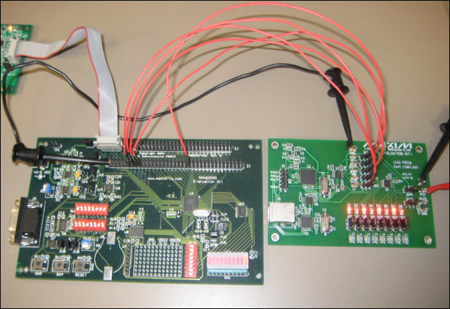
Remove the shunts from jumpers JU1–JU5. The system is configured by connecting pin 2 of JU1–JU5 (which corresponds to DIN, CLK, LE, DOUT, and active-low OE) of the MAX6970 EV kit board to the MAXQ2000 EV kit board (Figure 2). Move the shunt on jumper JU14 to the 2–3 position and apply a 3.3V supply to the VCC pad of the MAX6970 EV kit. Before turning on the power supply, ensure that the grounds from the MAXQ2000 and MAX6970 EV kits are connected together. All other jumpers on the MAX6970 EV kit should remain in their default positions of 1–2. Figure 3 shows the actual setup between the MAXQ2000 and MAX6970 EV kits.
Figure 2. Hardware configuration block diagram.
More detailed image (PDF, 1.75MB)
Figure 3. MAXQ2000 EV kit and MAX6970 EV kit setup.
Displaying an LED SequenceThe MAXQ2000 EV kit has a pushbutton (SW5), which will be used to select the LED sequence. Push down on the button for approximately 500ms and the first sequence of LEDs will turn on. The program consists of five different LED sequences , as shown in Table 1. Each bit of the 8-bit data sent to the slave corresponds to a LED on the MAX6970 EV kit. When the pushbutton count is 1, the sequence 0x55 will turn on for 250ms, alternate to 0xAA, and light up for 250ms. This sequence will repeat itself until the next time that SW5 is pressed. If SW5 is pressed during push count 5, then the next sequence will return to push count 1.
Table 1. Pushbutton Sequence Order
| Push Count | Sequence |
| 1 | 0x55, 0xAA |
| 2 | 0xFF, 0x00 |
| 3 | 0x01, 0x02, 0x04, 0x08, 0x10, 0x20, 0x40, 0x80 |
| 4 | 0x80, 0x40, 0x20, 0x10, 0x08, 0x04, 0x02, 0x01 |
| 5 | 0x01, 0x03, 0x07, 0x0F, 0x1F, 0x3F, 0x7F, 0xFF |
Firmware OverviewThe example MAXQ IAR Workbench C program files initialize the MAX2000 serial interface to communicate with the MAX6970. The serial interface clock is 8MHz when the system clock of the MAXQ2000 is 16MHz.
IAR Embedded Workbench is a registered trademark of IAR Systems AB.
MAXQ is a registered trademark of Maxim Integrated Products, Inc.
Rigid PCB Assembly = Rigid Printed Circuit Board Assembly, which means the PCB Board is rigid. For rigid PCB , if need be SMT assembly by machine, just need to add tabs/boaders on the PCB board for assembly. Zhongfeng would manufacture the rigid PCB boards follow the design file, source the components follow the BOM file and do the PCB Assembly job follow the assembly drawing and the pick&place file. After PCB assembly done, the components would be mounted on the PCB boards tightly and connected each other through the copper circuits. We call such board as PCBA board or rigid custom PCBA board.
Depends on the components assembly types, it have THT PCB assembly, SMT PCB Assembly , one sided SMT and THT PCB assembly, two sided SMT and THT PCB assembly.
Depends on the PCB type, it have Rigid PCB assembly, Flex PCB Assembly and Flex-Rigid PCB Assembly.
Also we would call some PCB assembly types as Prototype PCB Assembly, Mass PCB Assembly , Turnkey PCB Assembly, LED PCB Assembly and BGA PCB Assembly , etc.
With our 15years professional experience, we are available for all types of PCB assembly service from prototype to mass production, available for 01005, 0201, 0.3mm BGA, 0.3mm QFP.
PCB Assembly Capabilities
|
Quantity |
1 pcs - 1,000,000 pcs |
|
Assembly type |
SMT, THT or Hybrid |
|
Parts procurement |
Full turnkey (ZhongFeng provide all components) |
|
Partial turnkey ( Customer provide the main components and ZhongFeng provide the rest) |
|
|
Kitted (Customer provide all components) |
|
|
Component types |
SMT 01005, 0201, BGA 0.3mm pitch, QFP 0.3mm pitch, etc. |
|
Test |
Visual Inspection, AOI, Custom testing, ICT, FCT, Test jig |
PCB Assembly Products Show

PCB SMT Assembly Factory Show


Rigid PCB Assembly
Rigid PCB Assembly,Rigid PCB Assembly Prototype,Rigid PCB Board Assembly,OEM Rigid PCB Assembly
ZhongFeng Electronic Technology Co., Limited , https://www.dopcba.com