ESP (Electronic Stability Program) is an iconic invention of automotive electronic control. Different R & D institutions have different names for this system, such as the early Bosch (BOSCH) company called Automotive Dynamics Control (VDC), and now Bosch and Mercedes-Benz companies are called ESP; Toyota is called car stability Control system (VSC), vehicle stability assistance system (VSA) or vehicle electronic stability control system (ESC); BMW is called Dynamic Stability Control System (DSC). Although the names are not the same, they all add a lateral stability controller on the basis of traditional automotive dynamics control systems, such as ABS and TCS, to control the distribution and amplitude of lateral and longitudinal forces in order to control the car's performance under any road conditions. Dynamic sports mode, which can improve the dynamic performance of the car under various working conditions, such as braking, slipping, driving, etc. ESP has been mass-produced abroad, and it is still in the research stage in China. There is still a lot of work to be done to achieve industrialization.
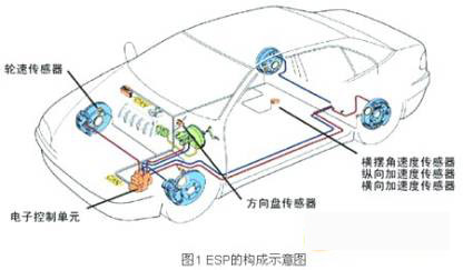
Figure 1 shows a schematic diagram of the structure of an automobile ESP. Its electronic components mainly include an electronic control unit (ECU), a steering wheel sensor, a longitudinal acceleration sensor, a lateral acceleration sensor, a yaw rate sensor, and a wheel speed sensor. ESP is an important electronic control system to ensure driving safety. The normal operation of each sensor is the basis for effective control. This paper introduces the characteristics of common ESP sensors, designs the sensor hardware interface and software interface, and is verified in the actual vehicle test.
2. Introduction of common ESP sensors
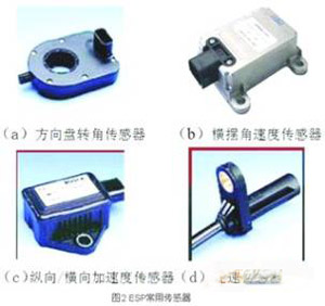
As shown in Figure 1 and Figure 2, the commonly used sensors of ESP are as follows.
1. Steering wheel angle sensor
The ESP recognizes the driver's operating intention by calculating the size of the steering wheel angle and the rate of change of the angle. The steering wheel angle sensor converts the steering wheel angle into a signal that can represent the driver's desired driving direction. The steering wheel angle is generally determined according to the photoelectric code. The code wheel installed on the steering column contains the encoded rotation direction, angle, etc. information. The information on this code disc is scanned by a proximity photocoupler. After turning on the ignition switch and turning the steering wheel angle sensor through a certain angle, the processor can determine the current absolute steering wheel angle through the pulse sequence. The communication between the steering wheel angle sensor and the ECU is generally done via CAN bus.
2. Yaw rate sensor
The yaw rate sensor detects the deflection of the car along the vertical axis, and the magnitude of the deflection represents the stability of the car. If the deflection angular velocity reaches a threshold, indicating that the vehicle is in a dangerous condition of slippage or tail flicking, ESP control is triggered. When the vehicle deflects around the vertical axis, the vibration plane of the micro-fork in the sensor changes, and the yaw rate is calculated by the change in the output signal.
3. Longitudinal / transverse acceleration sensor
The acceleration sensors in ESP include longitudinal acceleration sensors along the vehicle's forward direction and lateral acceleration sensors perpendicular to the forward direction. The basic principles are the same, but they are installed at an angle of 90 °. ESP generally uses a micro-mechanical acceleration sensor. Inside the sensor, a small piece of dense material is connected to a movable cantilever, which can reflect the longitudinal / lateral acceleration of the car. Its output is about 2.5V at static, positive The acceleration corresponds to a positive voltage change, and the negative acceleration corresponds to a negative voltage change. Each 1.0 to 1.4V corresponds to a 1g acceleration change. The specific parameters vary depending on the sensor.
4. Wheel speed sensor
When detecting the wheel speed signal on the car, the most commonly used sensor is an electromagnetic induction sensor. The general practice is to install the sensor on the non-rotating part of the wheel assembly (such as the knuckle or axle head) and the guide that rotates with the wheel. The gear ring made of magnetic material is opposite. When the ring gear rotates relative to the sensor, due to the change in reluctance, an alternating voltage signal is excited on the sensor. The frequency of this alternating voltage is proportional to the wheel speed. The ECU uses a special signal processing circuit to convert the sensor signal to the same. Frequency square wave, and then calculate the wheel speed by measuring the frequency or period of the square wave.
In the original ESP system, the longitudinal / lateral acceleration sensor and the yaw rate sensor were implemented separately. Now, the sensor cluster mode is basically used. The three sensors are designed as a whole, and the ECU is connected with the CAN bus communication. Figure 3 shows the sensor assembly produced by SIMENS VDO and BEI.

In order to add new ESP functions and to better control the stability of the entire vehicle, such as mountain maintenance control (HHC) and wire control (SbW), Bosch proposed the modular HW and SW concepts and developed the third generation Highly flexible and low-cost chronic sensor assembly DRS MM3.x.
Three, ESP commonly used sensor interface design
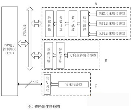
The block diagram of the design made in this paper is shown in Figure 4. In the figure, the signal of the steering wheel angle sensor is processed by the microcontroller and sent to the ECU through the CAN bus (B in Figure 4); the yaw rate sensor and the longitudinal / transverse sensor are designed in the same because of the similar signal characteristics and installation position In the module (A in Fig. 4); because ESP has high requirements for the real-time nature of the signal of the wheel speed sensor, after signal conditioning, it is directly sent to the ECU (C in Fig. 4). In A and B of Fig. 4, need the microprocessor to deal with the signal and transmit the data through CAN bus, this text chooses SAK-C164CI of Infineon Company. The chip is designed for automotive applications, built-in AD converter, input signal capture, quadrature decoder, fast operation speed, very suitable for ESP sensor signal processing.
1. Steering wheel angle sensor interface
The output of the steering wheel angle sensor is a quadrature coded pulse. The quadrature-encoded pulse consists of two pulse sequences with varying frequencies and a fixed phase offset of a quarter period (90 °), as shown in Figure 5. By detecting the phase relationship of the two signals, it can be judged as clockwise and counterclockwise, and the signals are counted up / down accordingly to obtain the current cumulative value of the count, that is, the absolute rotation angle of the steering wheel, and the rate of change That is, the angular velocity can be measured by the signal frequency. In addition, the steering wheel angle sensor has a zero output signal. When the steering wheel is in the middle position, the signal outputs 0V, otherwise it outputs 5V. Through this signal, the absolute rotation angle can be calibrated online.

The interface circuit between C164CI and steering wheel angle sensor is shown in Figure 6. A quadrature decoder with incremental encoding is built in the chip. The decoder uses the two pins of timer 3 (T3IN, T3EUD) as the input of quadrature pulse. After the relevant registers are correctly set, the data register of timer 3 The value is proportional to the steering wheel angle, so it is convenient to calculate the angle of rotation. The steering wheel angle sensor used in this paper corresponds to 44 pulses per revolution. Set the data register of timer 3 to T3. The rotation rate can be obtained through calculation.
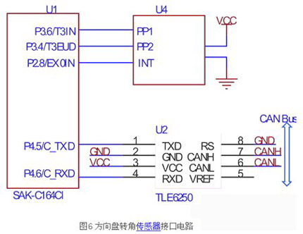
The microcontroller sends the calculated parameters to the ECU via CAN.
2. Wheel speed sensor interface
According to the signal characteristics of the wheel speed sensor introduced in the previous section, the interface circuit is designed as shown in Figure 7.
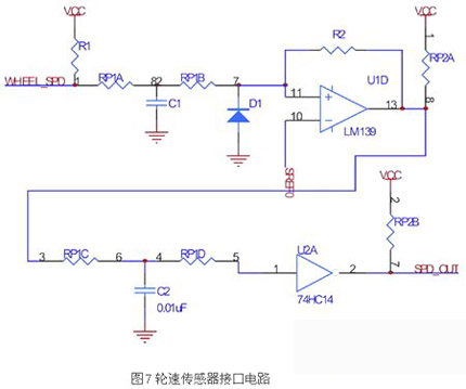
The circuit uses two-stage filtering and shaping to ensure that the wheel speed signal will not be lost at very low speeds, and at the same time avoid signal interference caused by suspension vibration. In the figure, the first-stage hysteresis comparison is introduced by resistor R2, while the second-stage hysteresis comparison is introduced using 74HC14.
3. Yaw angular velocity, longitudinal / lateral acceleration sensors
The installation position of the yaw angular velocity and longitudinal / lateral acceleration sensors are basically the same, and the output is an analog of 0V-5V. Due to the consistent signal fluctuation characteristics caused by car bumps, they are packaged in the same module. The hardware interface is shown in Figure 8, which implements hardware analog pre-filtering to suppress high-frequency noise components in the analog signal from the sensor and prevent aliasing during sampling. The op amp uses LMX324 with rail-to-rail output.
By adjusting the parameters of each resistance-capacitance element in FIG. 8, the filter cutoff frequency and the delay size can be set. During the operation of the car, when driving on a better road, the delay should be as small as possible due to the better signal. When driving on a bumpy road, the filtering effect is expected to be better. However, once the frequency characteristics of the hardware filter are designed and cannot be modified in real time, it is necessary to design the digital filter link in the software. Commonly used in digital filtering are Wiener filter, Kalman filter, linear predictor, and self-applicable filter. Here, the first-order low-pass filter with small calculation amount and good real-time performance is selected.

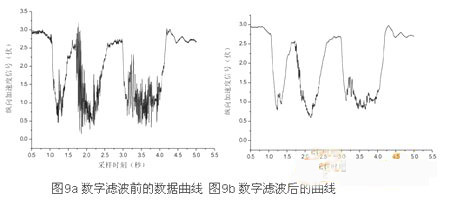
The choice of k depends on the current road conditions, and the current road conditions are identified by the original signal before digital filtering. The microcontroller packs the filtered signal, the original signal, the value of k, and the road surface recognition result, and sends it to the ECU via the CAN bus. Figures 9a and 9b are a set of comparative curves of the longitudinal acceleration sensors collected in the real vehicle test on bumpy roads, respectively.
This article discusses the structural characteristics and signal characteristics of commonly used sensors in ESP systems, and designs the signal processing interfaces of each sensor, including hardware interface circuits and software processing schemes. An integrated module containing yaw angular velocity and longitudinal / lateral acceleration sensors is designed, and data transmission is performed with the ECU via CAN bus, which has good anti-interference and reliability. The design of this article has been verified in the actual vehicle test.
Tws Bluetooth Earphone is amazing, true wireless design but give you 360° double surround stereo sound. One for two with smart function, two phones or computers can be connected/used simultaneously. And also smart safe charging, give you a greater choice.
Compared with traditional wired earphones, true Wireless Bluetooth Earphones bring you new experience that are more portable and easy to use. It can work within the range of 10-15 meters from your mobile phone, not only to avoid the entanglement of cable, but also to prevent the loss of mobile phones in a certain range. TWS Bluetooth Earphone has more convenient multiple functions that can not be replaced by the cable headphones.
As the stereo Bluetooth Headset of XT series, our company USES the chip above CSR4.2 and the real copper ring and graphene speaker to realize the sound quality similar to high resolution audio. Our company has applied for patents from China, Japan and the EU, as well as various certificates such as CE, ROHS, FCC, SGS, etc., contributing a lot to the worldwide music fans to enjoy high-quality music everywhere.
Tws Bluetooth Earphone,Bluetooth Earpiece,Wireless Bluetooth Headset,Wireless Bluetooth Earphones
ShenDaDian(China) Digital Electronics Co.,Ltd , http://www.btearbuds.com