1 Introduction
The continuous development of science and technology and economy has provided a broad market for the application of LED display. As a media carrier, LED display has become an indispensable part of film and television performances, large-scale song and dance, variety show, and also the darling of urban construction such as public media, outdoor advertising, and lighting projects.
As the mainstream of current multimedia display terminals, people have higher and higher requirements for display quality of flat panel displays. As one of the important parameters for evaluating the display quality of flat panel displays, gray level control capability has long been a concern. The gray level control ability is represented by the number of gray levels. The so-called gray level quantity refers to the gray level level that can be controlled. The current market LED large screen display product gray level is generally more than 12bit, but the existing The grayscale test technology standard is still based on the 8-bit grayscale test. This test is far from satisfying the dual requirements of high speed development of technology and market. Therefore, a method for detecting the ability of gray level control above 8 bits is needed. means.
In this paper, the acquired gray scale incremental distortion is analyzed, and the statistical results of the distortion amplitude are used to calculate the ability of the LED large screen display product gray level control. The experimental results show that the proposed method has good practicability.
2 current LED display gray level detection method
According to the "SJ/T1128122007 LED display test method", the gray level inspection method is as follows: the environmental illuminance change rate is less than ±10%, the instrument acquisition range is unchanged throughout the test process; the software is started, the gray level is increased step by step, and the brightness of the display should be As the gray level rises, it rises monotonously. The highest standard is 128
It can be seen that the currently used LED display test method is a linear detection method. If the number of linear grayscale displays of the LED display exceeds 8 bits, additional data input devices and software are required, which is very inconvenient. In fact, the LED display test method measures the minimum linear grayscale resolution of the display, rather than the true gray level of the display. In theory, the finer the minimum linear gradation resolution of the display, the higher the gradation correction depth, and the better the accuracy of the gradation correction, the better the ability to display the effective gradation.
The method of determining the minimum linear gray scale resolution of the LED display screen can reflect the effective gray level level of the display screen from some aspects, but cannot directly evaluate the display gray level characteristic of the display screen. In addition, most of the current LED display grayscale parameters are above 12bit, and in the photoelectric conversion process, due to some subtle situations, some correspondence imbalance occurs, so only know the minimum linear grayscale resolution of the LED display. The rate does not fully represent the accuracy of its gray level control.
3 image data and gray level function relationship
For historical reasons, current standard video image data can cause grayscale distortion problems if used directly on flat panel displays. Gray level refers to the brightness level of the display. In the original display system, the display terminal was a CRT device, and since the CRT device was not a linear light-emitting device, there was severe distortion in reproducing gray scales. This distortion is caused by the non-linearity of the entire image information transmission system by the mutual conversion and transmission between the photoelectric signals. This nonlinearity is mainly introduced by three aspects:
(1) Non-linearity between the output luminance signal value of the imaging device and the actual luminance Li; (2) non-linearity between the luminance signal values; (3) between the display device reproduction luminance Lo and the transmitted luminance signal value Nonlinearity.
The relationship between the reproduced luminance Lo and the actual luminance Li can be expressed as:
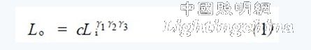
Where c is a proportional coefficient; γ1, γ2, and γ3 are the (1), (2), and (3) partial nonlinear correction coefficients, respectively. In order to ensure correct reproduction of the gray level, the image data must be gamma corrected before transmission. Let γ1γ2=γ, γ3=γCRT then the formula (1) can be changed to:
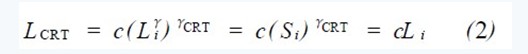
The LCRT is the CRT reproducing brightness, Li is the actual brightness, γ is the pre-correction coefficient of the original transmission, γCRT is the CRT display characteristic coefficient, and Si is the original image data. It can be known from equation (2) that the standard image data currently used is the γ-corrected original display image data, and the digitized data formed after direct quantization also contains γ-corrected information, and the digitized image data is displayed by the same CRT. When the final display device completes the final image display, the original gray level can be reproduced correctly.
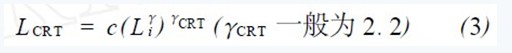
The display characteristics of the aforementioned CRT are:
The display characteristics of the LED display are:
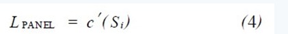
Where c and c' are scale factors. Taking the display of 256 gradation display data as an example, the display characteristics of the CRT and the display characteristics of the flat panel display are as shown in Fig. 1 (a) and Fig. 1 (b), respectively.
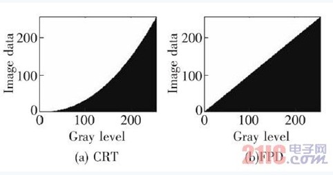
Figure 1 Display characteristics of CRT and FPD
If the image data cannot be processed correctly when the image is displayed, it will cause distortion of the gray level and greatly reduce the display quality of the image. As shown in Fig. 2, Fig. 2(a) is the original image data after γ correction. Due to the display characteristics of the LED display, the actual display result has a large error with the expected actual result; Fig. 2(b) shows The deviation of the actual image data from the ideal image data at each gray level.
The gamma correction was originally introduced only to eliminate the nonlinearity error of the entire display system. Since the dominant position of the display terminal has been occupied by the CRT for a long time, the γ-corrected raw image data has been determined. For standard image data. In the short term, the standard for such image data cannot be replaced by new standards. In order to ensure the correct reproduction of the gray level on the flat panel display, gray scale correction must be performed during the display process.
Figure 2 shows the deviation of the actual and ideal image data on the LED. (a) original image data; (b) deviation of image data.
4 Gray Matter Difference Detection and Analysis Method and Implementation
4.1 test
The test instruments used in the experiment mainly include Kemei CS2100A color brightness meter, Kemei CL2200 color illuminometer and temperature and humidity meter.
The test conditions are as follows:
(1) The relative environmental illuminance change is less than ±10%;
(2) The test distance is between 3. 5 and 5.0 m, and the relative test position does not change during the test;
(3) The minimum area of ​​the test unit shall not be less than 0. 5m2;
(4) The collection area shall not be less than 4 × 4, 16 pixels.
The test method is as follows:
(1) The collecting instrument is placed horizontally on the ground, and is kept at the same height as the screen to be tested. The lens field of view completely covers the screen to be tested, and the integrated surface is collected to cover at least 16 pixels.
(2) Under the black screen state, test the screen brightness and the ambient illuminance average, and record the ambient temperature and humidity values;
(3) After the screen is fully loaded for 30 minutes, the test is started;
(4) Randomly select 9-point test in full screen, and test each group of test points and each level of gray for 5 times, take the average value and record.
4.2 Data Analysis
According to the gamma correction principle, the display data of any LED display is currently 8~10bit. Taking 8bit display data as an example, the grayscale capability of the screen is set to 8bit. Under the premise of correct display of grayscale, the following grayscale is obtained. The function is shown in Figure 3.
Figure 3 LED shows the gray function
The horizontal coordinate in the figure is the 8-bit display data (d) of the screen display: 0~255, and the ordinate is the relative brightness value (L) of the display screen corresponding to these display data.
After the data is normalized, the gray level difference distribution of the function is shown in Fig. 4.
Figure 4 LED shows the level difference distribution of 8bit gray level
The horizontal coordinate in Fig. 4 is still the 8-bit display data (d) of the screen display: 0~255; the ordinate is the gray level difference between the relative brightness values ​​of the screen display with 8-bit gray scale display accuracy corresponding to the display data. (ΔL). It can be seen that due to the problem of precision, the increment of the gray scale difference has distortion; at the same time, it can be seen that the distortion of the quantization reflects the gray scale control precision of the display screen to some extent.
If the gray level capability of the screen is increased to 10 bits, the gray level difference distribution is as shown in FIG. 5.
The horizontal coordinate in Fig. 5 is still the 8-bit display data (d) of the screen display: 0~255; the ordinate is the gray level difference between the relative brightness values ​​of the screen display with the display accuracy of 10 bit gray level corresponding to the display data. (ΔL).
Through analysis, the grayscale incremental distortion amplitude of the display with 8bit grayscale display capability is about 4‰, and the display grayscale incremental distortion amplitude of the 10bit grayscale display capability is controlled at about 1‰, so the data is passed. The analysis can obtain the control precision of the gray level.
Figure 5 LED shows the difference distribution of 10bit gray level
5 experimental results and discussion
If the accuracy of the measuring instrument is ±0.1 cd/m2 and the ambient illuminance is below 5lx, the amount of change is described with reference to the previous measurement conditions. The grayscale incremental distortion detection method can initially obtain the grayscale control of the 8~15bit display. Precision. However, under certain practical conditions, due to measurement environment and instrument errors, display grayscale control.