2.3 brake pressure regulator
This article refers to the address: http://
The brake pressure regulator is an ABS actuator that consists of a solenoid valve, a reservoir and a return pump motor for each wheel cylinder. The brake pressure regulator is connected in series between the master cylinder (master cylinder) and the wheel cylinder (wheel cylinder), and its function is to automatically adjust the brake pressure of the brake cylinder (wheel cylinder) according to the control command of the ABSECU. To keep the wheel at an optimum slip ratio between 10% and 30%.
Some of the brake pressure regulators are fitted with the master cylinder, which reduces the number of brake hydraulic tubes. At present, most vehicles install brake pressure regulators on the front side of the engine compartment for easy access. The Odyssey sedan belongs to the latter.
Most brake pressure regulators are integrated with the circuit control unit of ABSECU, which reduces the wires between the motor, solenoid valve and ECU, and simplifies the wiring harness, but the brake fluid that is frequently braked heats up to the ABSECU circuit chip and switch. Unfavorable. The Odyssey's ABSECU is located on the mounting bracket in front of the passenger's side skirting board (to be removed during inspection) (Fig. 1), while the brake hydraulic regulator is located on the left front side under the hood.
For the car ABS, most of the brake pressure regulators are drawn from the master cylinder (vacuum booster), two seamless steel pipes, controlled by four or eight solenoid valves inside the regulator, and then four The seam steel pipes are respectively connected to four wheel-distributing wheel cylinders, which are called "four channels". Individual control of the four wheel brakes is implemented.
There are 4 or 8 solenoid valves in the regulator; if there are 4, each wheel steel has 1 three-position three-way solenoid valve; if there are 8, each wheel cylinder has 2 Two-position three-way solenoid valve, these two solenoid valves, one normally open, one normally closed, closed and opened separately when energized.
2.3.1 Hydraulic regulator with 8 solenoid valves
Each wheel has a two-valve two-position solenoid valve - a hydraulic regulator with eight solenoid valves, as shown in Figure 5.
The two-valve two-position solenoid valve controls the hydraulic oil to route two solenoid valves - a normally closed solenoid valve EV2.
2.3.1.1 Pressure rise phase (Figure 5a)
When the brake pedal is depressed, a braking force is generated in the wheel cylinder. At this time, the two ball valves 5 and 6 of the electric liquid return pump 4 are closed, the electromagnetic valve EV1 is in a normally open state in which the valve is not working, and the EV2 is in a normally closed state in which the EV2 is not in operation. . At this time, the brake system pressure increases normally. ABS has not been activated and the wheel decelerates smoothly. The function of the brake release valve 7 installed in parallel (parallel) with the solenoid valve EV1 is to ensure that the pressure of the wheel cylinder is rapidly lowered when the driver relaxes the brake pedal.
2.3.1.2 Pressure maintenance phase (Figure 5b)
This condition is implemented when the brake pressure is too high and the wheel is in danger of being locked. When the limit (threshold value) of the wheel deceleration is exceeded, the ABSECU receives the information of the wheel speed sensor 8, and after calculation processing, the command is issued to close the normally open solenoid valve EV1, and the normally closed solenoid valve EV2 is still in a resting state - remains closed. The cycle between the solenoid valve and the wheel is independent, and the brake pressure of the wheel cylinder remains the same regardless of the force applied by the driver to the brake pedal. If the driver relaxes the brake pedal, the brake release valve 7 ensures that the wheel cylinder pressure is quickly eliminated, although the EV1 is closed.
2.3.1.3 Pressure drop phase (Figure 5c)
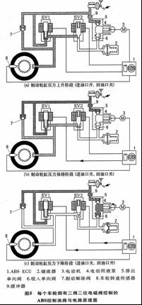
When the wheel movement develops toward the lock-up trend and exceeds the allowable slip ratio, the ABSECU senses the signal through the wheel speed sensor 8, and the solenoid valve EVI continues to be turned off by the energization control, the solenoid valve EV2 is turned on by the energization control, and the ABSECU simultaneously controls the return pump. When the motor is working, the brake fluid is returned to the brake master cylinder through the liquid return pump 4, and the deceleration braking of the wheel becomes slow and transitions to re-acceleration. When the solenoid valve EV2 is opened, the accumulator 2 quickly sucks in the brake fluid, so that the pressure is rapidly lowered when the EV2 is opened, while avoiding the impact of the valve 6, and the buffer 9 is used to reduce the pulse vibration on the brake pedal.
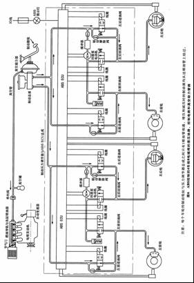
Figure 6 is a schematic diagram of the operation of four wheel brake cylinders combined with eight solenoid valves in an EHCU brake pressure regulator. Figure 6 mainly shows these key elements: 1 the relationship between the vacuum-assisted brake master cylinder and the engine intake pipe. The two four-channel hydraulic lines are arranged diagonally by x (cross), that is, the left rear wheel and the right front wheel share a hydraulic oil circuit; the left front wheel and the right rear wheel share a hydraulic oil circuit. Even if there is a brake oil circuit that causes two wheels on the diagonal to malfunction, the brake fails, and another two-wheel brake on the diagonal line is effective. 3 Two valves per wheel and two valves, mainly for each solenoid valve oil circuit, only two kinds of working conditions, the current of the control coil is only two kinds of working conditions: power-on and power-off, easy to control, and the reliability is greatly improved. If it is a single valve three-position, the ABSECU must control the output current in OA, 2A, 5A current, in order to make the regulating valve in the boosting, holding pressure and decompression conditions, the solenoid valve structure is more complicated. 4 Figure 6 shows the four wheel speed sensor signals of the four wheels sent to the ABSECU; the execution instructions of the ECU are output to the control coils of the eight solenoid valves, respectively. Each solenoid valve is only under the action of the control coil magnetic force and spring tension. 2 kinds of working conditions: the normally open inlet valve is energized and closed; the normally closed solenoid valve is energized to open. 5 The load-sensing proportional valve is often connected in series in the rear brake hydraulic circuit (not shown in Figure 6) to control the change of the braking force ratio of the front and rear wheels to ensure that the front wheels have the first time when braking with different loads. The tendency to lock in the rear wheel prevents the more dangerous side slip tails and effectively improves the directional stability during braking.
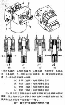
The ABS actuators of the eight solenoid valves are shown in Figure 7. In contrast, the structure of the two-position solenoid valve per wheel is simpler than that of the single-valve three-position three-way solenoid valve, and the reliability is also higher. The normally open solenoid valve is energized to close against the spring force (Fig. 7a, 7b); the normally closed solenoid valve is opened against the spring force when energized (Fig. 7c, 7d).
2.3.2 Hydraulic regulator with 4 solenoid valves
The oil circuit and circuit principle of the single-position three-position solenoid valve per wheel are shown in Fig. 8. Compared with the two-valve two-position solenoid valve of each wheel of Fig. 5, there are many similarities: 1 brake master cylinder to hydraulic regulator has one hydraulic oil pipe connected (4 wheels and 2 tubes); 2 hydraulic regulator to each wheel brake The clamp (wheel cylinder) has one seamless steel pipe connected (four rounds of four steel pipes); the 3ABSECU to the liquid return pump motor has only one wire connected. The difference is that the former has two solenoid valves and two wires. The latter has only one solenoid valve and only one wire. The working process is as follows.
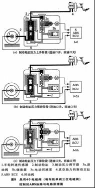
2.3.2.1 Boosting process
When each single solenoid valve is assembled, the main spring and the secondary spring connected to the oil inlet valve and the return oil valve have a certain pre-stress, and the two springs are reversely actuated, because the main spring has a large elastic force, so that The inlet valve is normally open (Fig. 8a) and the return valve is closed. When the driver starts to step on the brake pedal, the pressure in the brake master cylinder is increased by the master cylinder interface, the oil inlet valve 3a, and the wheel cylinder 2, and although no current flows into the solenoid valve ( I=0A), however, the solenoid valve is in the “boost stateâ€. Therefore, if the ABS fails to work, the brake pressure can be directly applied to the brake wheel cylinder to ensure the normal braking effect of the original vehicle, that is, the brake. The pressure can be increased both in the normal braking without ABS and in the case of ABS control.
2.3.2.2 Pressure holding state
When the controller excites the solenoid coil with a medium current I=2A, the electromagnetic force acting on the armature and causing it to move upward can only close the inlet valve by overcoming the elastic force of the main spring, and the return valve is maintained under the action of the secondary spring. Closed state, thus cutting off the passage between the brake master cylinder and the brake wheel cylinder, and also does not communicate with the liquid return port, so that the brake fluid in the brake wheel cylinder is sealed and the pressure is kept constant, at this time, the solenoid valve It is in a state of pressure.
2.3.2.3 Decompression state
When the ABSECU activates the solenoid valve with the maximum current I=5A, the electromagnetic force acting on the armature can completely overcome the elastic force of the main spring and the secondary spring, and the oil return valve 6 is opened, and the oil inlet valve remains closed. The brake fluid flows back to the accumulator 3b of the hydraulic regulator through the solenoid valve return port, so that the pressure of the brake wheel cylinder drops, the brake shoe relaxes the pressure on the brake disc (drum), and the solenoid valve is in a decompressed state. (Figure 8c). Once the pressure of the wheel cylinder is released, the solenoid valve is switched to the "pressure hold" state or the normal brake (non-excitation current) state, ready for pressure rise.
Automatic Coffee Machine,Coffee Machine,Cappuccino Maker,Single Serve Coffee Maker,Drip coffee maker,POD coffee maker,Espresso coffee maker
FOSHAN FORTUNE ELECTRICAL APPLIANCE CO.,LTD , https://www.coffelady.com