In traditional high-fidelity systems, audio amplifier technical specifications always emphasize the quality of sound quality, but the degree of power loss is rarely considered. However, with the growth of the portable high-fidelity field in the audio industry, the shortcomings of traditional amplifier devices, especially its low efficiency, have become an urgent problem to be solved.
Traditionally, audio playback equipment uses so-called class AB amplifiers, which have low distortion and produce high sound quality. However, the operation of the class AB amplifier explains its low efficiency: the internal voltage of the amplifier will decrease as the output voltage decreases. The transistors of the amplifier consume too much power. Therefore, as the output speaker power decreases, the efficiency of the system decreases.
For high-fidelity devices powered by power, this is not a big problem; but for battery-powered audio devices, such as mobile phones and MP3 players, this is a considerable problem because the power consumption of audio amplifiers is It occupies a considerable proportion in the entire system. Taking MP3 players as an example, the power consumption of audio amplifiers accounts for up to 80% of the overall power consumption.
Therefore, audio equipment designers have been looking for ways to enhance class AB topology. The question to be discussed in this article is whether the power saving effect achieved by using new technologies such as Class G or Class H is worth it? If the system designer uses Class G or Class H amplifiers, then the two methods of Class G or Class H are used. Is the difference in power consumption large enough to affect the overall power budget?
System requirements for portable audio equipment
Audio amplifiers used in handheld devices usually drive a 16? Or 32? Impedance, which often consumes most of the device's power budget. This means that any improvement in power amplifier efficiency can significantly improve the efficiency of the entire device and battery life. For more information, please log in to the electronic enthusiast website (http: //)
As we have seen, the most important parameter that affects the efficiency of traditional audio amplifiers is the peak output power. This is mainly determined by the type of headphones used by the device: Compared with headphones, the peak power requirements of the earbuds are lower, but the typical output power range of the two channels is 4mW each, and the total power can be up to 2 × 30mW.
For a 32? Impedance headphone speaker, if the output power is 30mW, an amplifier output swing of ± 1.38Vpk is required. The amplifier stage for this application will require an additional voltage space of 100-200mV. Therefore, the power supply voltage of the headphone amplifier will be 2 × 1.5V = 3.0V
To avoid using output DC decoupling capacitors that are too large for the application, a charge pump is generally used to generate the negative power rail required by the headphone amplifier, so that the audio output runs near the battery ground. This configuration is the "true ground" headphone amplifier. It uses 1.5V positive power supply; -1.5V power rail comes from the charge pump.
The most commonly used battery type is a lithium ion battery, which generally produces 3.6V output. The high-efficiency DC / DC step-down converter can convert the battery output to a positive 1.5V power supply without significant losses. This is a common configuration for class AB amplifiers. A typical system block diagram is shown in Figure 1.
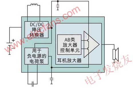
Figure 1: True ground headphone amplifier.
(DC / DC buck converter, charge pump for negative power supply, class AB amplifier control unit, headphone amplifier)
The high-quality DC-DC converter can convert the lithium-ion battery voltage from 3.7V to a fixed 1.5V output voltage with up to 93% efficiency. Compared with the case where the amplifier transistor consumes 2.2V (3.7V battery voltage-1.5V operating voltage), this method is of course more efficient.
However, this does not obscure the fact that transistors still consume a lot of power except at high output voltage levels. To solve this problem, the power configuration of the amplifier itself needs to be changed, which is why the development of Class G and Class H amplifiers.
Match input voltage and output voltage
The power value of the audio amplifier is the peak power value. In fact, the time required for this maximum supply voltage is extremely short; the audio signal has a very wide dynamic range. Most of the time, the output voltage is below 0.5V, while the power supply voltage of the amplifier can reach 1.5V. The difference between the output voltage and the power supply voltage comes from the part consumed by the internal amplifier transistor, which is the main cause of power loss.
To solve this problem, the power supply voltage of the amplifiers used in Class G and Class H amplifiers must meet the required output power to a certain extent. Class G amplifiers generally have two supply voltage levels. The higher supply voltage level is determined by the maximum output power required. The lower supply voltage level is determined by the minimum supply voltage. The amplifier can operate at this voltage, and this voltage is higher than the total harmonic distortion (THD) threshold.
Compared with Class G amplifiers, Class H amplifiers can smoothly adjust the output voltage according to the requirements of the output signal. Therefore, unlike Class G amplifiers, Class H amplifiers are not limited to two or three fixed output voltages. It can smoothly convert the lowest allowable power supply voltage from the buck converter to any discrete output voltage.
Therefore, the Class H amplifier can work with a power supply voltage that closely matches the actual output voltage; reduce the difference between the power supply voltage and the output voltage, and reduce the required power consumption. (See Figure 2)
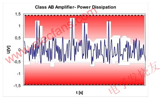
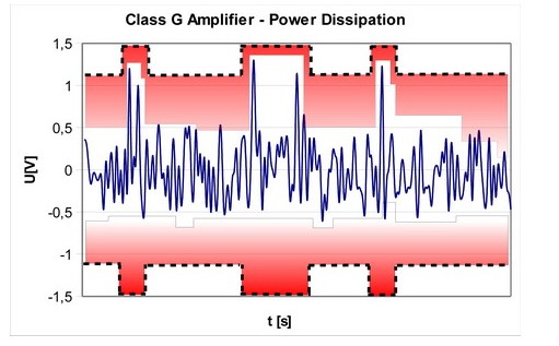

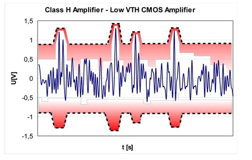
Figure 2: Power consumption of different amplifier configurations
In fact, since audio equipment operates at the lowest allowable supply voltage most of the time, the power consumption of Class G and Class H amplifiers, and the proportion of headphones to the total system power consumption, are more or less limited by the total harmonic distortion threshold The lower level of the power supply is determined. We call this important parameter, the minimum supply voltage, VSUPMIN.
Figure 2 shows the difference in power consumption of different types of amplifiers. The positive and negative voltages of each amplifier are marked with black dotted lines. Class G amplifiers can support two different output voltages: 1.5V and 1.2V (VSUPMIN). On the other hand, Class H amplifiers support additional voltage levels between 1.5V and 1.2V. Class G and H amplifiers can significantly reduce power consumption.
In addition, compared to Class AB amplifiers, the implementation of Class G or Class H topology is not very complicated and the cost has not increased much (Figure 3 is a simplified block diagram of Class G / Class H amplifiers). The main difference from Class AB amplifiers is that the DC / DC converter no longer has a fixed output voltage. The variable voltage output needs to add a feedback signal from the amplifier output stage to the DC / DC converter in order to adjust the output voltage according to the audio signal.
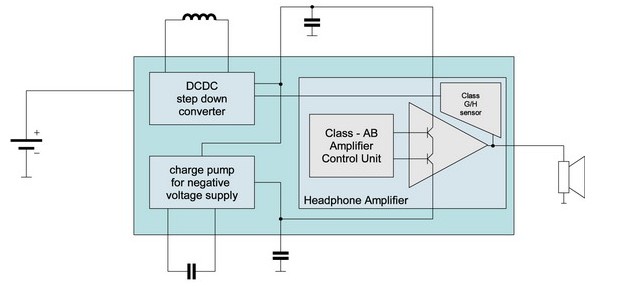
Figure 3: Block diagram of a Class G / H amplifier.
(DC / DC buck converter, charge pump for negative power supply, class AB amplifier control unit, headphone amplifier, G / H sensor)
Degree of difference between the best and worst class H or class G amplifiers
Based on cost and availability considerations, headphone amplifiers are generally manufactured using CMOS technology. Although the ideal value of VSUPMIN depends on the circuit design of the amplifier, in practice it often depends on the lowest threshold of the CMOS technology used to manufacture the amplifier.
In today's amplifier design, the definition of VSUPMIN is 2 × VTH + Vdsat. If the CMOS process for manufacturing the device can support lower VSUPMIN values ​​by implementing lower transistor thresholds, a better result can be achieved. For example, if the amplifier stage is running at a minimum supply voltage of ± 1.2V, it will increase power consumption by 30% compared to an amplifier operating at ± 0.9V that plays the same audio signal.
This is exactly the promise of Austrian Microelectronics' special LowVT CMOS process. These processes have been used to produce brand new AS3561 devices. The AS3561 is a Class H amplifier that provides a headphone amplifier with a supply voltage as low as ± 0.9 V. Combined with a high-efficiency DC-DC converter and an adaptive charge pump, it can minimize power consumption: the battery voltage of 2 x 0.1mW playback is 3.6V, and the typical current consumption is only 1.7mA. The difference in power consumption between this high-efficiency architecture and the G and AB architectures is shown in Figure 4.
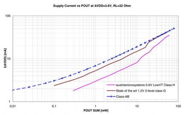
Figure 4: Comparison of power consumption between Class H, Class AB and Class G
in conclusion
Compared with the widely used Class AB amplifiers, Class G and Class H audio amplifiers can dynamically adjust the power supply voltage, greatly improving power supply efficiency. However, analysis of devices that work at the total harmonic distortion threshold of the amplifier most of the time shows that Class H amplifiers manufactured using low-voltage threshold process technology can save an additional 30% of power.
The Push Button Switches, also known as the control button (referred to as the button), is a low-voltage electrical appliance that is manually and generally can be automatically reset. The Push Button Starter Switch is usually used to issue a start or stop command in the circuit to control the turning on and off of electrical coil currents such as electromagnetic starters, connectors, and relays.
The On Off Push Button Switches refers to a switch that pushes the transmission mechanism with a button to make the movable contact and the static contact open or close and realize circuit switching. It is a master control device with a simple structure and a wide range of applications. In the electrical automatic control circuit, used to manually send control signals to control connectors, relays, electromagnetic starters, etc.

This Pushbutton Switches is a kind of electric device that is used to switch on and off the small current circuit when the action is released. Generally used in AC and DC voltage below 440V, the current is less than 5A in the control circuit, generally do not directly manipulate the main circuit can also be used in the interconnection circuit. In actual use, in order to prevent desperation, different marks are usually made on the buttons or painted with different colors, and the colors are red, yellow, blue, white, black, green, and the like.

The Momentary Push Button Switch could be divided into metal push button switches and Led Light Switches and ordinary snap button type, mushroom head type, self-locking type, self-resetting type, rotary handle type, with indicator light type, lighted symbol type and key type, etc., with single button and double Buttons. Generally, it adopts a water-storage structure, which consists of a button cap, a return spring, a static contact, a moving contact and a casing. It is usually made into a composite type, and has a pair of normally closed contacts and normally open contacts, and some products can pass. The series connection of multiple elements increases the number of contact pairs. There is also a self-contained button that automatically holds the closed position when pressed, and can be turned on only after the power is turned off.
When the Metal Switches is not pressed, the movable contact is connected with the upper stationary contact. The pair of contacts is called a normally closed contact. At this point, the movable contact is disconnected from the following static contact. The pair of contacts is called a normally open contact: the button is pressed, the normally closed contact is open, the normally open contact is closed, and the button is released. Restore the original working state under the action of the return spring
Push Button Switches
Push Button Switches,Push Button On Off Switch,Push Button Switch Types,Square Push Button Switches
YESWITCH ELECTRONICS CO., LTD. , https://www.yeswitches.com