Based on the development of single-point thermal gas mass flowmeter, a hot gas mass flow test method based on multi-point measurement is proposed for the problems existing in gas mass flow measurement of large diameter or irregular pipeline. In this paper, a large number of experimental studies have been carried out on the temperature characteristics of sensitive components (hot film probes) and the multi-point test method using hot film probes as measuring points. The experimental results show that the multi-point test method is best in logarithmic linear method; the multi-point thermal gas mass flow test method can significantly improve the large deviation in some single-point measurement, the measurement accuracy can reach 1. 5% 4以上。 The expansion uncertainty is less than 3. 4%.
Key words: thermal mass flowmeter; test method; temperature correction; curve fitting; uncertainty
The thermal gas mass flow meter is a new type of gas flow measuring instrument developed on the basis of the early hot wire anemometer. It has been widely used in aviation, aerospace, energy, medicine, automobile industry and natural gas pipeline transportation industries. At present, the research and application of domestic thermal gas mass flow meters are still in the initial stage, and most products need to be imported, especially the thermal gas flow meters for gas flow measurement of large and medium-sized pipelines. Therefore, research on thermal gas mass flow meters will be of great significance to the development of China's national economy. Based on the development of single-point thermal gas mass flowmeter, the single-point measurement accuracy in the current large-diameter or irregular pipeline gas mass flow measurement is not high, and the differential pressure gauge pressure loss is too large and speed- The problem of measuring the area is difficult, and a thermal gas mass flow test method based on multi-point measurement is proposed.
1 Measurement principle and temperature characteristics of sensitive components
Thermal mass flow meters are classified into hot wire and hot film [1, 2] depending on the heating element. In this paper, a thin film platinum (platinum film resistor or platinum film probe) is used as a sensitive component. As a new type of temperature sensing element, platinum film resistor has the characteristics of small size, fast response, easy to match with integrated circuit, and has the advantages of wide temperature measurement range, high precision, good linearity and stable performance. It has a wide range of applications in the fields of temperature compensation, temperature and flow measurement and control.
When used as a flow sensor, the platinum film resistor has a great relationship with the ambient temperature due to the heat dissipation condition of the probe. The signal output will be affected by the change of the ambient temperature. In order to quantitatively grasp the temperature characteristics of the thermal probe, we heat it according to the thermal flowmeter. The probe operating temperature range is tested for the temperature characteristics of the hot film probe at different ambient temperatures. Place the hot film probe in a temperature-adjustable incubator, add a constant working current i to the probe, measure the voltage v across the probe under different working conditions, and then calculate the thermal film probe resistance. The thermal film probe temperature characteristics experimental device is shown in Figure 1.
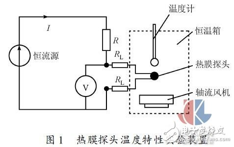
Since the working temperature of the hot film probe is difficult to measure accurately, in the static temperature characteristic experiment, the curve of the working resistance of the hot film probe with temperature is first established, that is, under the premise that the thermal film probe has no self-heating effect (working current ≤ 1 ma ), the thermal film probe resistance changes with the ambient temperature. According to the actual situation, this paper selects pt20 thermal film probe as the experimental research object.
The thermal film probe has no self-heating effect, and the relationship between the thermal film probe resistance and the ambient temperature is shown in Fig. 2.
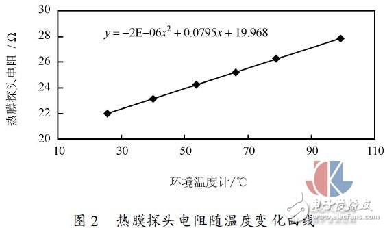
The relationship between the thermal film probe resistance rt and the ambient temperature t is established by the static temperature characteristic curve of the thermal film probe:
In the industry, a thin film platinum resistor is used as a temperature measuring element, mainly using a platinum resistance without the self-heating effect, and the current through the platinum resistance is generally not more than 1 ma. In this paper, a thin film platinum resistor is used as a heating element, and a large current is used to make the platinum film probe reach a certain working temperature by using its own thermal effect, as a measuring gas flow sensitive component.
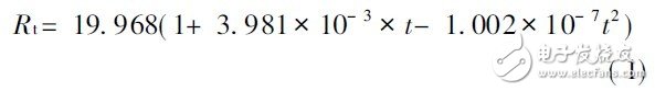
The thermal film probe is subjected to the same current (i = 70 ma) under different experimental conditions (u = 0 and u ≠0), and the relationship between the resistance rt and the ambient temperature t is shown in Fig. 3.
The thermal film probe under different experimental conditions (u = 0), the different working currents are applied to the thermal film probe, and the relationship between the resistance rt and the ambient temperature t is shown in Fig. 4.
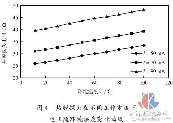
By analyzing Fig. 3 and Fig. 4, it can be concluded that the thermal film probe works in a constant current state, and its resistance changes almost linearly with the change of ambient temperature, that is, the difference between the operating temperature of the hot film probe and the ambient temperature is $t. constant. The heat dissipation caused by the forced convection of the hot film probe under different working conditions does not change with the change of the ambient temperature. For example, the heat dissipation caused by forced convection for the selected thermal film probe is about 31 mw. The operating temperature of the hot film probe increases as the operating current increases. For example, at an ambient temperature of 20 ° C, i = 50 ma, the hot film probe operating temperature is about 77 ° C; i = 70 ma, the hot film probe operating temperature is about 142 ° C; i = 90 ma, hot film probe The operating temperature is approximately 256 °C. So we can determine the operating temperature of the hot film probe by selecting the operating current of the hot film probe.
2 Multi-point test method analysis
The multi-point thermal gas mass flow meter mainly arranges a plurality of sensing elements in the cross-sectional diameter direction of the pipeline to detect the gas flow at different points in the pipeline section, as shown in FIG.
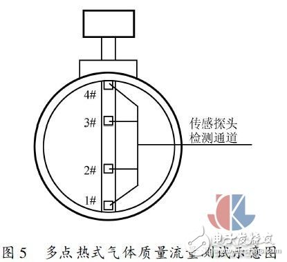
The multi-point thermal gas mass flow test method is based on the principle of velocity measurement of a constant velocity tube flowmeter [3, 4]. That is, the pipe section is divided into several parts with equal areas, and the characteristic point mass flow rate of each part is measured, and the average mass flow rate of this part is represented by the characteristic point mass flow rate. Multiplying the mass flow rate by the area of ​​this portion yields a mass flow through the small block area. Adding the mass flow rate of each small piece of material is the mass flow through the entire pipe. The key to the multipoint test method is how to determine the location and number of distribution of feature points. Multi-point detection sensors were designed by equal torus method, Chebyshev method and logarithmic linear method. The experimental pipe radius r = 30 mm is selected. The design divides the pipe section into two equal parts. Taking the center of the pipe as the origin, the distribution of the characteristic points of the multi-point detection rod is shown in Figure 6.
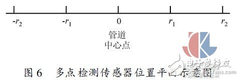
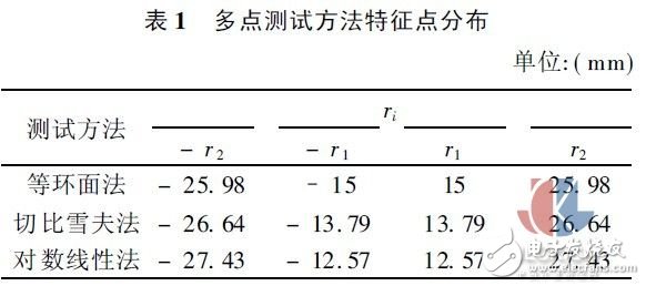
According to the values ​​of the feature points of the three methods given in References [5~6], the distribution positions of the multi-point detection sensor feature points under different test methods are calculated in turn as shown in Table 1:
3 temperature correction
The working principle of the thermal gas mass flowmeter is based on the forced convection heat transfer between the hot film probe and the fluid to be measured. The size of the output signal is not only related to mass flow, but also related to the temperature of the measured medium [1]. Therefore, when the temperature of the fluid in the measurement environment is different from the temperature of the calibration fluid, the accuracy of the measurement result will be directly affected, so the temperature correction of the thermal gas mass flowmeter must be performed.
The commonly used methods of temperature correction for thermal gas mass flow meters can be divided into two categories: analytical calibration methods and automatic calibration methods.
The analytical correction method requires a separate temperature sensor to detect the ambient temperature ta and then insert ta into the selected heat transfer relationship. In this method, the thermal film probe operates in a constant resistance state. With the application and development of computer and microelectronics technology, most of the current temperature corrections for thermal mass flowmeters use analytical correction methods [7,8]. The key to analytical correction is to determine the heat transfer relationship of the hot film anemometer, ie the output signal as a function of wind speed and temperature. At present, the research on the temperature correction of anemometer is basically to determine the heat transfer formula [7~9].
The automatic correction method, which adds a temperature sensor to the Wheatstone bridge, automatically compensates for changes in ambient temperature. At this time, the thermal film probe operates in a non-constant resistance state. The automatic calibration method used is to change the bridge arm resistance of the Wheatstone bridge from the thermal probe to a series-parallel circuit including a compensation resistor, as shown in Figure 7. Where rc is a platinum resistance with a positive temperature coefficient, which is placed in the same flow field as the thermal film probe rw.

The compensation circuit design is based on the temperature characteristics of the thermal film probe and the resistance temperature parameters that compensate for the platinum resistance. In order for the sensor output to not change with ambient temperature, it should theoretically be satisfied at any ambient temperature:
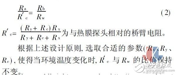
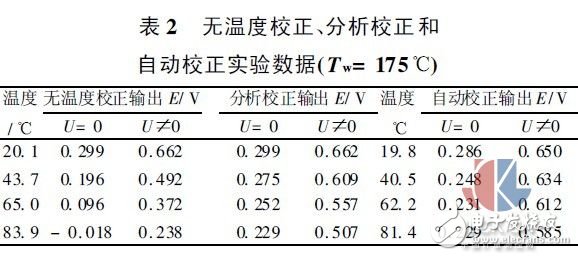
Table 2 shows the experimental data of the multi-point thermal gas mass flowmeter without temperature correction and the analysis correction and automatic correction respectively. Wherein, the analysis correction output corresponds to the same set of temperature values, and the automatic correction output corresponds to another set of temperature values.
The temperature drift of the thermal mass flow sensor can be divided into zero temperature drift and sensitivity temperature drift [10]. Zero-point temperature drift is the drift caused by temperature change when the sensor is at rest. It is expressed by tcr, see equation (3). Sensitivity temperature drift is the drift caused by temperature change when the sensor is in a certain flow state, expressed by t cs. See formula (4).
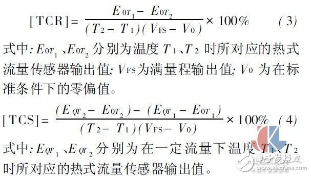
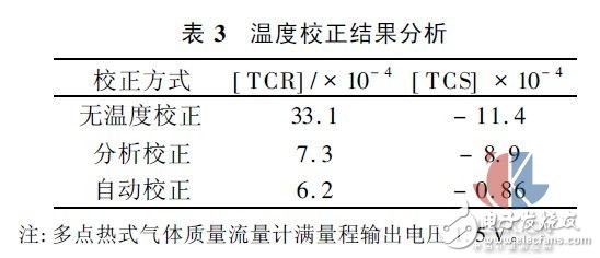
Table 3 shows the results of the temperature calibration before and after multi-point thermal mass flowmeter.
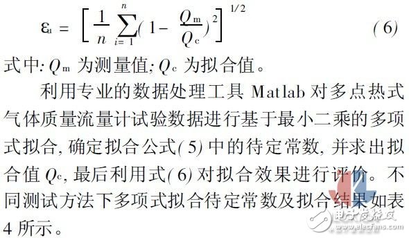
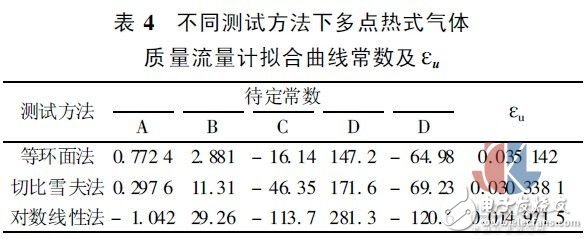
4 output signal calibration
At present, there are three main methods for fitting the characteristic curve of the thermal gas mass flowmeter, namely power law fitting, extended power law fitting and polynomial fitting. This paper uses a quadratic polynomial fit for analysis. The four-degree polynomial fitting formula of the multi-point thermal gas mass flowmeter can be expressed as


5 Uncertainty analysis
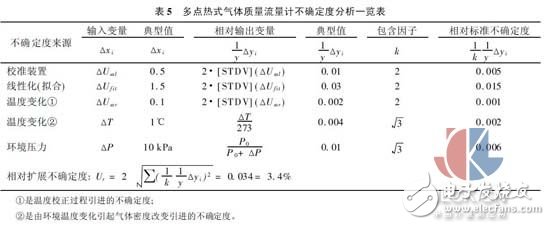
Multi-point thermal gas mass flowmeter measurement error consists of random error and systematic error. Random errors such as noise of the signal conditioning circuit; system errors such as calibration error, linearization error, error of the signal conditioning circuit, measurement error caused by the temperature of the measured fluid, etc. The noise of the signal conditioning circuit and the error of the signal conditioning circuit are one order of magnitude smaller than other errors, which can be ignored as a small error [12~13]. The uncertainty analysis of the multi-point thermal gas mass flowmeter is shown in Table 5 at the end of this paper.
6 Conclusion
(1) When the platinum membrane resistor is used as a flow sensor (large heating working current), its resistance temperature characteristic still has good linearity under different working conditions; when operating at constant current, its working temperature and ambient temperature The difference is basically constant.
(2) The output signal of the thermal mass flowmeter has a large temperature drift without temperature correction. After the temperature correction, the temperature drift of the system is obviously improved, and good results are obtained. At the same time, for the temperature correction method adopted in this paper, the temperature correction effect of the automatic correction method is better than the analysis correction method.
(3) The multi-point thermal gas mass flow test method can improve the large deviations in some single-point measurements and achieve better measurement accuracy.
Lithium Ion Battery,5G Integrated Battery,Custom Ups Lithium Ion Battery,Communication Ladder Backup Battery
Wolong Electric Group Zhejiang Dengta Power Source Co.,Ltd , https://www.wldtbattery.com