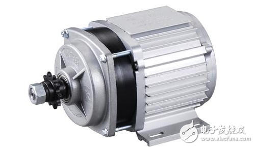
Motors, commonly referred to as electric motors, are devices that convert electrical energy into mechanical motion. These machines play a crucial role in various industrial applications, where they utilize the electrical power generated by generators to drive machinery and equipment. While the construction of a motor is similar to that of a generator, their working principles are essentially opposite. A motor receives electrical current to produce rotational movement, whereas a generator converts mechanical motion into electricity through the movement of a rotor within a magnetic field. To achieve a strong and stable magnetic field, both motors and generators typically use electromagnets.
**Motor Structure**
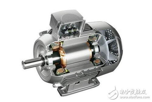
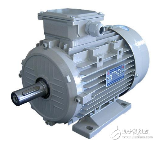
A three-phase asynchronous motor consists of two main parts: the stator and the rotor. The stator is the stationary component, made up of the motor housing, three sets of windings, and silicon steel laminations. The rotor, on the other hand, is the rotating part, which includes a silicon steel core with embedded windings. Bearings at both ends of the motor shaft support the rotor, while bearing caps prevent movement and oil leakage. Additionally, the motor may have blades at the end, secured with retaining rings for stability.
**Motor Maintenance Methods**
Proper maintenance is essential to ensure the longevity and efficiency of an electric motor. A typical maintenance process involves cleaning the rotor, replacing worn components such as carbon brushes, performing vacuum pressure impregnation with insulation paint, drying the components, and balancing the rotor. Regular inspections and care can significantly reduce the risk of failure.
1. Keep the motor’s environment dry and clean, ensuring that air vents are not blocked by dust or fibers.
2. If the motor frequently triggers its thermal protection, it may be due to overload or incorrect protection settings. Check both the motor and the control system before resuming operation.
3. Ensure proper lubrication of the bearings. After approximately 5,000 hours of operation, grease should be replaced or replenished. When replacing, remove old grease, clean the bearing with gasoline, and refill with ZL-3 lithium-based grease—half for 2-pole motors and two-thirds for 4, 6, and 8-pole motors.
4. As bearings age, vibration and noise may increase. Replace them when radial clearance exceeds acceptable limits.
5. When disassembling the motor, carefully remove the rotor from the non-extended end if possible, to avoid damaging the stator windings.
6. When rewinding the motor, always record the original winding specifications, including the number of turns, wire gauge, and coil shape. Never alter the design without consulting the manufacturer, as this can lead to performance issues or even damage.
**Motor Wiring Inspection**
Whether it's an AC or DC motor, the internal windings are connected according to specific configurations to the external circuit, a process known as motor wiring. Proper wiring is critical during installation. Before starting, familiarize yourself with the wiring diagram provided in the motor’s junction box. Different types of motors have different wiring methods, so following the correct procedure is essential.
For DC motors, the wiring is usually indicated on the junction box cover. Depending on the excitation method and load direction, the connections can be adjusted accordingly. However, reversing the armature and field windings in a DC motor can cause serious problems, such as uncontrolled acceleration or overheating. Therefore, it's important to ensure that the external wiring of the armature and field windings is correctly configured.
Before connecting the motor to the power source, check that all terminal connections are secure. Tighten any loose screws, and connect the shorting pieces based on the required wiring configuration. It is also recommended to perform an insulation test using a megohmmeter (shake table) with 500V voltage. For low-voltage motors, the insulation resistance should be greater than 0.5 MΩ.
After installation and wiring, several checks must be performed before commissioning:
1. Civil engineering work should be completed and cleaned.
2. Motor installation and inspection should be finalized.
3. Secondary circuits, such as control systems, should be fully tested.
4. The rotor should rotate smoothly without any obstruction.
5. All main circuit wiring must be securely fastened to prevent loose connections, which could lead to overheating or damage.
6. Other related systems should be verified for compliance.
Among these, the fifth point requires special attention. The main circuit includes all wiring from the power distribution panel to the motor terminals, including switches, contactors, fuses, and thermal relays. Ensuring tight connections is vital for safe and reliable motor operation.
During trial runs, monitor the motor’s current to ensure it stays within specified limits. Additionally, verify the direction of rotation, especially for DC motors, where swapping the armature or excitation leads will reverse the direction. Listen for any unusual noises, such as grinding or screeching, which may indicate a problem requiring immediate attention.
Withstand high voltage up to 750V (IEC/EN standard)
UL 94V-2 or UL 94V-0 flame retardant housing
Anti-falling screws
Optional wire protection
1~12 poles, dividable as requested
Maximum wiring capacity of 10 mm2
10 amp Terminal Blocks,high quality terminal connectors,10 mm² terminal blocks,BELEKS T10 series connector strips
Jiangmen Krealux Electrical Appliances Co.,Ltd. , https://www.krealux-online.com