60v to 12v converter circuit diagram (detailed five analog circuit design schematics)

**60V to 12V Converter Circuit Diagram (1)
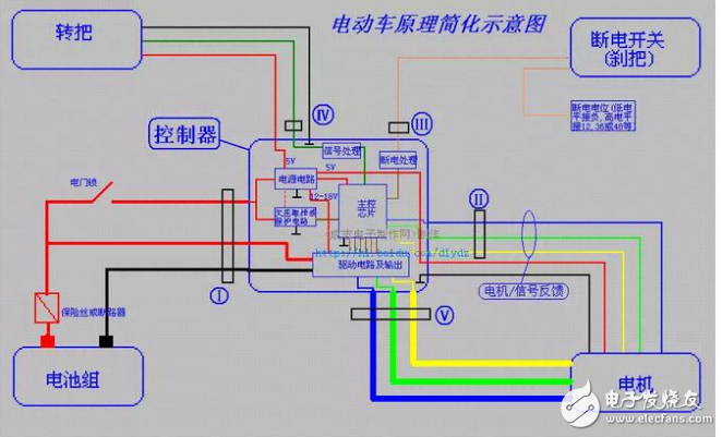
** 越来越多的消费者在电动车辆配件出现问题时,倾向于自行排查问题。他们需要更换部件,并且会附上接线图以便大家更好地理解。谈到电动车报警器的接线方式,虽然原理简单,但必须找到转换器的正负极。如何将纺织电动车的60V铅酸电池与另一块60V电池并联,同时将铅酸电池和锂电池的正极连接到50A电源二极管上。

Electric car 60v converter to 12V wiring diagram

Electric car 60v converter to 12V

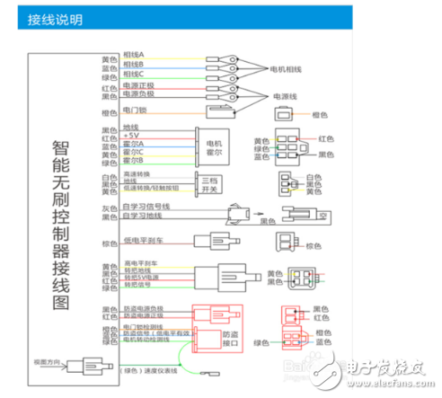
DC/DC converters, commonly known as power converters, are used in electric vehicles to step down the voltage. These devices usually have some power margin, but if your audio system requires more power, it's recommended to add another voltage converter to avoid damaging the system. The electric vehicle converter typically has three wires: red, yellow, and black. The red wire is for the input (lock line), the yellow wire provides the 12V output, and the black wire serves as the ground. **Two important points to note:** 1. Make sure the positive and negative poles of the power supply are not reversed, or you risk damaging the speaker or the converter. 2. Pay attention to the maximum output current of the converter. If the converter can only supply 1A, the total power of the connected devices should not exceed 10W to prevent damage. **Wiring an Electric Vehicle with a 12V Converter** This is straightforward. First, understand the basic principle of the converter, which typically converts 48–64V to 12V. The converter will have three wires: red for high-voltage input (36–64V), black for the negative terminal, and yellow for the 12V output. You can install the converter near the front of the vehicle. Connect the red wire to the electric door lock output, the black wire to the common negative, and the yellow wire to the switch of the light you want to install.

60v to 12v converter circuit diagram (detailed five analog circuit design schematics)

**Electric Vehicle Controller Wiring Diagram** When replacing an electric vehicle controller, you often see a colorful and complex wiring setup that can be overwhelming. So how can you quickly identify and connect the controller to the vehicle? Here’s a method: today we’ll take a closer look at what each wire on the controller represents. First, determine the positive and negative poles of the power supply and the electric door lock line. Use a multimeter set to DC mode. Connect the black probe to the battery’s negative terminal and use the red probe to test the voltage. The one showing a higher voltage is the positive pole. The electric door lock line is unique because it only has voltage when the key is turned on. Next, connect the three lines from the key switch, power cord, and electric door lock. The controller’s power cord is usually thick red for the positive and thick black for the negative. After connecting, turn on the key and check the voltages. The power supply line should read about 5V, and the Hall line should also show around 5V. Then, connect the third voltage to the white learning line. If the motor rotates when unplugged, there may be an issue with the throttle. Usually, connections are made by color. If not, you may need to test using a switch. After the motor runs smoothly, disconnect the brake wires, Hall lines, and instrument lines. What does each wire on the controller mean? (The image below shows a detailed schematic of a high-end electric vehicle controller.)

60v to 12v converter circuit diagram (detailed five analog circuit design schematics)

Understanding the various lines on the controller: Locate the 5 Hall lines from the motor’s 3-phase lines, then find the 3 throttle lines and 2 brake lines. When disassembling the battery, you’ll see the “+” and “-” terminals. If the motor isn’t working properly, the Hall sensor might be faulty. To test the Hall sensor: charge the vehicle and connect the lines. Set the multimeter to DC 20V. Confirm the controller outputs 5V, then connect the black probe to the Hall ground. Touch the red probe to each signal line while gently turning the motor by hand. A healthy Hall sensor will show 0V–5V pulse voltage. If no pulse is detected, the Hall is likely damaged. The instrument line: Disassemble the meter to find the two wires—one connected to the anti-theft interface and the other to the controller’s instrument line. To find the throttle line: Remove the throttle to locate the three wires. You can identify them by color or use a multimeter to measure. For the brake line: When the brake lever is removed, you’ll find two wires. This is a normally open switch, so you can connect them directly to the controller’s brake power-off input. After installation, push the vehicle forward, connect the learning line, and turn on the electric door lock. The system will enter self-learning mode. If the motor runs in the wrong direction, adjust the speed control knob to reverse it, then disconnect the learning line.

Vapme Shisha 30000

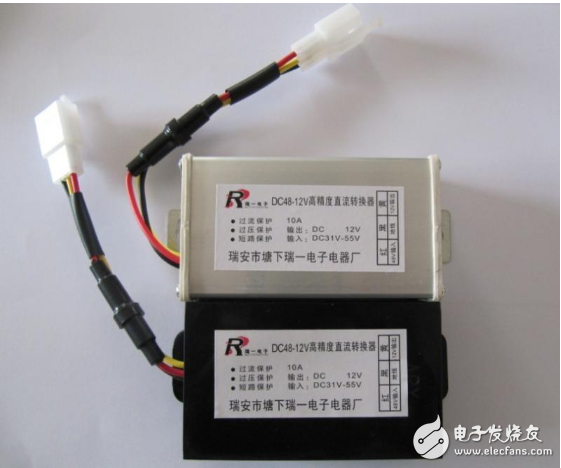
Shenzhen Essenvape Technology Co., Ltd. , https://www.essenvape.com

Posted on