When designing an analog-to-digital converter (ADC) circuit, one of the most common challenges is ensuring proper protection for the ADC input under overvoltage conditions. Overvoltage can occur in various scenarios and requires careful consideration to avoid damaging the ADC or affecting system performance. While each ADC vendor may have slightly different recommendations, the core principles remain similar across the board. This article will explore potential issues, their frequency, and practical solutions for protecting ADC inputs during overvoltage events.
Overvoltage typically occurs when the driver amplifier's supply voltage exceeds the ADC’s input range. For instance, if the amplifier is powered by ±15 V, but the ADC only accepts a 0 to 5V range, the ADC could be exposed to excessive voltages that might cause permanent damage. This situation is common in industrial applications, such as programmable logic controllers (PLCs), where high-voltage rails are used to drive signal conditioning stages. If a fault occurs on the amplifier rail, the ADC may suffer from either exceeding its maximum ratings or experiencing disruptions in multi-ADC systems where synchronization is critical. This article focuses primarily on precision Successive Approximation Register (SAR) ADCs like the AD798x series, but the concepts apply broadly to other ADC types as well.
Consider the circuit shown in Figure 1. It represents a typical design for the AD798X family of PulSAR ADCs. In this configuration, a protection diode is connected between the ADC input, reference, and ground. These internal diodes can handle currents up to 130mA, but only for short durations—making them unsuitable for repeated or prolonged overvoltage events. Some devices, such as the AD768X/AD769X family (e.g., AD7685, AD7691), use the VDD pin instead of the reference for protection. This setup is generally more robust because VDD is a stable rail and less susceptible to noise or interference.
In the scenario depicted in Figure 1, if the amplifier is connected to a +15 V rail, the protection diode tied to the reference node may activate. If the reference node isn't driven by a strong buffer, it could be pulled above the ADC’s absolute maximum voltage rating, potentially causing damage. As shown in Figure 3, if the driver tries to pull the reference to 8 V while the reference is set at 5 V, the ADC could be affected. Many precision voltage references lack sinking capability, which can lead to instability or incorrect readings. Even with a strong reference driver, slight deviations from the nominal value can still impact accuracy.
In multi-ADC systems that share a single reference, overvoltage on one channel can affect all conversions, leading to inaccurate results. Additionally, if the recovery time from a fault is long, subsequent conversions may also be compromised. To mitigate these risks, several protection strategies can be employed. One of the most effective is using a Schottky diode (such as the BAT54 series) to clamp the amplifier output within the ADC’s input range. This approach is illustrated in Figures 2 and 3.
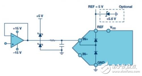
Figure 2: A modified ADC circuit with added Schottky and Zener diode protection. The Schottky diode is chosen for its low forward voltage drop, which allows it to trigger before the internal ADC protection diodes. This helps limit current flow into the ADC and provides additional safety. In cases where the reference lacks sufficient current sinking capability, a Zener diode or clamp circuit can be added to the reference node. For example, a 5.6V Zener diode is often used with a 5V reference to prevent over-pulling.
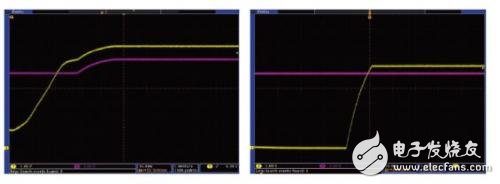
Figure 3: Comparison of ADC input and reference voltage with and without a Schottky diode. The left image shows the ADC input without protection, while the right image includes a Schottky diode to limit overvoltage.
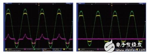
Figure 4: ADC input (yellow), driver input (green), and reference voltage (purple). The right image includes a Schottky diode (BAT54S) to protect against overvoltage, while the left image does not.
22000mAh Fast Charging Battery
22000mAh Fast Charging Battery,22000mAh battery with fast charging,22000mAh Battery Bank,220Wh Battery Bank
Shenzhen Jentc Technology Co., LTD , https://www.phenyee.com