LED (Light Emitting Diode)
Light-emitting diodes first appeared in the 1960s, and now we can often see these diodes as indicators for electrical and electronic equipment. An LED is a semiconductor device whose electrical performance is the same as that of an ordinary diode, except that when the LED is turned on, it emits light. Since the LED is solid, it can extend the life of the sensor. As a result, photosensors using LEDs can be made smaller and more reliable than incandescent light sensors. Unlike incandescent lamps, LEDs are shock and shock resistant and do not have a filament. In addition, the light energy emitted by the LED is only equivalent to a portion of the light energy generated by an incandescent lamp of the same size. (Excluding the laser diode, it has the same principle as the ordinary LED, but it can generate several times of light energy and can reach a farther detection distance). LEDs emit infrared light that is invisible to the human eye and can emit visible green, yellow, red, blue, blue-green, or white light.
Modulated LED sensor In 1970, people discovered that LED has a better advantage than long life, that is, it can switch at a very fast speed, and the switching speed can reach KHz. By modulating the receiver's amplifier to the transmitter's modulation frequency, it can only amplify the optical signal that oscillates at this frequency. We can compare the modulation of light waves to the transmission and reception of radio waves. By tuning the radio to one station, you can ignore other radio signals. The modulated LED emitter is similar to a radio wave transmitter and its receiver is equivalent to a radio.
People often have a misunderstanding: It is believed that because the infrared light emitted by the infrared LED is invisible, the energy of the infrared light will certainly be strong. The amount of energy of the modulated photosensor is not much related to the wavelength of the LED light wave. An LED emits very little light energy and is modulated to make it very energy. An unmodulated sensor is only mechanically shielded by the use of a long-focus lens, so that the receiver can only receive light from the transmitter in order to make its energy very high. In contrast, a modulated receiver can ignore ambient light and respond only to its own light or light with the same modulation frequency. Unmodulated sensors are used to detect ambient light or infrared radiation, such as fresh red hot bottles. If other sensors are used in this application, they may malfunction. If a metal emits light much stronger than the surrounding light, it can be reliably detected by the surrounding light receivers. The ambient light receiver can also be used to detect outdoor light.
However, it does not mean that the modulated sensor will not be disturbed by ambient light, and it will cause problems when used in a strong light environment. For example, an unmodulated photoelectric sensor can operate normally when it is directed at sunlight. Every one of us knows that it's easy to ignite a piece of paper with a magnifying glass that collects sunlight on a piece of paper. Imagine replacing the glass with a sensor lens and replacing the paper with a phototransistor so that we can easily understand why it would not work when the modulated receiver is pointed at the sunlight. This is because the surrounding light source saturates it.
The modulated LED improves the design of the photosensor, increases the detection distance, and expands the angle of the beam. People gradually accepted this reliable and easy-to-align beam. By 1980, non-modulated photoelectric sensors gradually withdrew from the stage of history.
Infrared light is the most efficient light beam, and it is also the light beam that best matches the phototriode in the spectrum. However, some sensors need to be used to distinguish colors (such as color mark detection), which requires the use of visible light sources.
In the early days, color-coded sensors used incandescent lamps as light sources and used photocell receivers until they invented high-efficiency visible LEDs. Most color-code sensors now use a variety of colors of visible-light LED emitters. Modulated sensors tend to sacrifice response speed to obtain longer detection distances because the detection distance is a very important parameter. Unmodulated sensors can be used to detect small objects or objects that move very fast. The response speed required for these applications is very fast. However, high-speed modulation sensors can also provide very fast response speeds to meet most inspection applications.
Ultrasonic Sensors Acoustic waves emitted and received by acoustic sensors have vibration frequencies that exceed those of human ears. It determines the position of an object by calculating the time it takes for the sound wave to return from the emission to the receiver. For an over-the-beam ultrasonic sensor, if the object obstructs the sound wave from the transmitter to the receiver, the sensor detects the object. Unlike the photoelectric sensor, the ultrasonic sensor is not affected by the transparency and reflectance of the measured object, so it is not suitable to use a photoelectric sensor for detection in many cases where the ultrasonic sensor is used.
If the installation space of the optical fiber is very limited or the operating environment is very harsh, we can consider using optical fiber. The optical fiber is used together with the sensor and is a passive component. In addition, the optical fiber is not interfered by any electromagnetic signals, and the electronic components of the sensor can be isolated from other electrical interferences.
The optical fiber has a plastic optical core or a glass optical core, and the optical core is covered with a metal sheath. This metal skin has a lower density than the optical core and therefore has a low refractive index. The light beam shines on the boundary between the two materials (within a certain range of angles of incidence) and is totally reflected back. According to the optical principle, all light beams can be transmitted by optical fibers.
Two incident beams (incidence angle within the acceptance angle) are reflected multiple times along the length of the fiber and exit from the other end. Another incident light that exceeds the acceptance angle range is lost in the metal sheath. This angle of acceptance is slightly greater than the double maximum angle of incidence because the fiber will refract slightly when it is injected into the denser optical fiber material. The transmission of light inside the fiber is not affected by whether the fiber is bent (the bending radius is greater than the minimum bending radius). Most optical fibers are flexible and can be easily installed in tight spaces.
Glass fiber glass fiber consists of a very fine (50 μm diameter) glass fiber filament. A typical fiber optic cable consists of hundreds of individual glass fiberglass jackets with a metal sheath. The fiber optic cable is protected by a sheath. The ends of the cable are available in various sizes and shapes, and a strong transparent resin is poured. The inspection surface is optically polished and is very smooth. This meticulous grinding process can significantly increase the optical coupling efficiency between fiber bundles.
The fiber bundles inside the glass fiber can be arranged compactly or at random. Compactly arranged glass optical fibers are commonly used on medical devices or borescopes. Each fiber needs to be carefully arranged from one end to the other so that a very clear image can be obtained at the other end. Because this type of fiber is very expensive and most fiber applications do not require a very clear picture, most glass fibers have their fiber bundles randomly arranged. This type of fiber is very inexpensive, and of course, the resulting image It's just some light.
The protective layer outside the glass fiber is usually a flexible stainless steel sheath, but also some PVC or other flexible plastic material. Some special optical fibers can be used in special spaces or environments, and their detection heads are made in different shapes to suit different detection requirements.
Glass fiber is rugged and reliable, can be used in high temperature and chemical environment, it can transmit visible light and infrared light. The common problem is that the glass fiber is broken due to frequent bending or bending radius. For this application, we recommend using plastic optical fiber.
Plastic Optical Fibers Plastic optical fibers consist of a single fiber bundle (typical beam diameter 0.25 to 1.5 mm), usually PVC sheath. It can be installed in a small space and can be bent at a very small angle.
Most plastic optical fibers have their probe heads made of a probe or threaded cylindrical shape and are not machined at the other end to allow customers to cut them short according to their use. Bonner's plastic optical fiber is equipped with a fiber optic knife. Unlike glass optical fibers, plastic optical fibers have a high degree of flexibility. Plastic optical fibers with protective skins are suitable for mounting on reciprocating mechanical structures. Plastic optical fibers absorb light waves of a certain wavelength, including infrared light, so plastic optical fibers can only transmit visible light.
Compared with glass fibers, plastic fibers are susceptible to high temperatures, chemicals, and solvents.
Both fiber-optic and fiber-optic fiber optics and plastic fiber optics have both "single"-to-radio, and "forked"-reflexes. A single fiber can transmit light from the transmitter to the detection area or from the detection area to the receiver. The bifurcated fiber has two distinct branches that transmit emitted light and received light, respectively, so that the sensor can transmit the emitted light to the detection area through one branch while transmitting the reflected light back to the receiver through the other branch.
The straight-reverse glass fiber has a fiber bundle at the test head that is randomly arranged. The straight-reverse plastic optical fiber has a bundle of fibers arranged along the length of the optical fiber.
Special Applications of Optical Fibers Since optical fibers are less affected by the use environment and resist electromagnetic interference, they can be used in special applications such as vacuum-conducting optical fiber (VFT) for vacuum environments and optical fibers for use in explosive environments. In these two applications, the specially designed optical fiber is installed in a special environment and led out through a flange to an external sensor. The sizes of the optical fiber and the flange are various. Intrinsically safe sensors, such as NAMUR type sensors, can be used directly in special or potentially explosive environments.
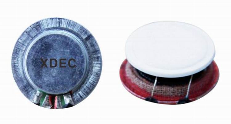
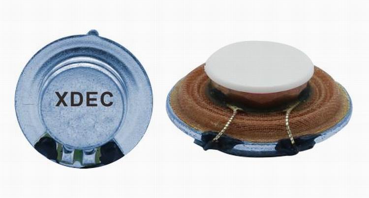
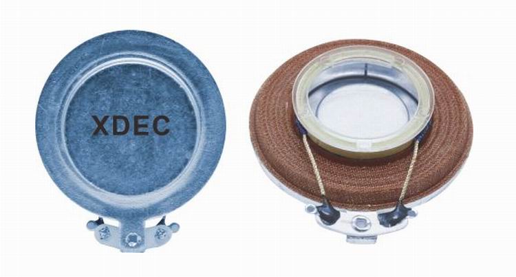
Vibration speaker:
Vibration speaker is a kind of speaker unit which is made from vibration principle. It is also called resonance speaker. Vibration Speakers have no diaphragms and also called exciters. They drive any solid plane surface they contact and made that surface sound, so people can have original sound from different materials. Vibration speakers have a special penetrability which traditional speakers don`t have. These kind of speakers are mainly used for digital audio speakers, music massage facilities and music treatment facilities.
Our main vibration speakers include:
1) From the diameter: we have speakers in diameter of 18mm ~ 44mm.
2) From the power output, we have speakers of 2W ~ 15W.


FAQ
Q1. What
is the MOQ?
XDEC: 2000pcs for one model.
Q2. What is the delivery lead time?
XDEC: 15 days for normal orders, 10 days for urgent orders.
Q3. What are the payment methods?
XDEC: T/T, PayPal, Western Union, Money Gram.
Q4. Can you offer samples for testing?
XDEC: Yes, we offer free samples.
Q5. How soon can you send samples?
XDEC: We can send samples in 3-5 days.
Vibration Speakers
Vibration Speaker,Vibration Driver,Vibro Speaker,Vibration Bluetooth Wireless Speaker
Shenzhen Xuanda Electronics Co., Ltd. , https://www.xdecspeaker.com