1 Introduction
With the development of modern science and technology, PLC has been widely used in industrial control microcomputers.
At present, the industrial robot joints are mainly controlled by AC servo system. In this study, the SIEMENSS-200 programmable controller with mature technology, convenient programming, high reliability and small volume is applied to the controllable circulating current reversible adjustment system to develop the robot. Joint DC servo system for servo control of industrial robot joints.
2 industrial robot joint DC servo system
The industrial robot joint is driven by a DC servo motor , and the forward and reverse rotation of the motor is controlled by the circulating reversible speed control system to achieve the purpose of servo control of the industrial robot joint.
2.1 Control system structure
The system adopts SIEMENS7-200 PLC, plus D/A digital-to-analog conversion module, which turns PLC digital signal into analog signal, and adopts BT-I variable current speed control system (mainly by speed regulator ASR, current regulator ACR, circulation regulation). The ARR, the positive group trigger GTD, the reverse group trigger GTS, and the current feedback unit TCV) drive the DC motor to operate, and drive the robot joint to operate according to the control requirements. The system structure is shown in Figure 1.
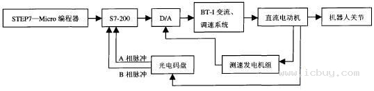
Figure 1 Schematic diagram of the robot joint DC servo system
2.2 System working principle
The system principle is shown in Figure 2. The main circuit of the controllable circulating current reversible speed control system adopts the cross-connection method. One secondary winding of the rectifier transformer is connected to the Y-type, the other is connected to the △-type, and the phase of the two AC power supplies is staggered. °, the frequency of its circulating current is l2 times the power frequency. In order to suppress the AC circulation, two equalizing reactors are connected between the two groups of controllable rectifier bridges, and a smoothing reactor is still retained in the armature circuit.
The control circuit is mainly composed of the speed regulator ASR, the current regulator ACR, the loop regulator ARR, the positive group trigger GTD, the reverse group trigger GTS, and the current feedback unit TCV (see Fig. 2), wherein the synchronization signals of the two sets of flip-flops They are taken from the synchronous transformer corresponding to the rectifier transformer.
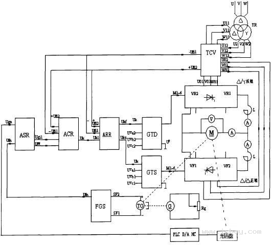
Figure 2 Schematic diagram of industrial robot joint DC servo system
When the system is given zero, the speed regulator ASR and the current regulator ACR are locked by the zero speed blocking signal. At this time, the system mainly consists of a loop regulator ARR to form a constant current system with cross feedback. Due to the influence of the circulation, the two sets of thyristors are in the rectified state, the output voltages are equal in magnitude and opposite in polarity. The DC motor armature voltage is zero, the motor stops, and the output current flows through two sets of thyristors to form a circulation. . The circulation should not be too large, and is generally limited to about 5% of the rated current of the motor. During the forward start, as the speed signal Ugn increases, the blocking signal is released, the speed regulator ASR is positive, and the motor is running forward. At this time, the positive current feedback voltage +Ufi2 reflects the sum of the motor armature current and the circulating current; the reverse group current feedback voltage -Uril reflects the armature current, so the main current can be adjusted. The loop given signal -Ugih and the cross current feedback signal -Ufil applied to the input of the positive loop regulator have minimal impact on this regulation process. The input voltage of the reverse loop regulator is (+Uk)+(-Ugih)+(Ufi2). As the armature current increases continuously, when it reaches a certain level, the circulation automatically disappears, and the anti-group thyristor enters Inverted state. The opposite is true for reverse startup. In addition, the controllable circulation reversible speed control system still has the process of inverting the bridge, reverse braking and feedback braking when braking. Since the starting process is also a process in which the circulation is gradually reduced, the circulation of the system reaches a maximum when the motor is stopped. The circulation helps the system to cross the switching dead zone and improve the transition characteristics.
Table Top Cooker,Three Burner Gas Cooker,Ce Tempered Glass Gas Cookers,3 Burner Gas Stove With Ce
Xunda Science & Technology Group Co.ltd , https://www.xundatec.com