In the era of rapid development of information technology, computer, communication, consumer electronics and other technologies, although computers and networks have penetrated into every corner of daily life, a variety of new embedded access Equipment has become the current mainstream product. Any ordinary person may have dozens of embedded electronic products, ranging from watches, mobile phones, mp3 players, PDAs and other micro-digital products, to smart home appliances, network appliances, and car electronics. Technology. As an important research branch of embedded technology, robotics, which is currently in full swing at home and abroad, various industrial robots and service robots have begun to be applied to people's production and life. The advantages of using robots have been It is widely recognized and is becoming part of our daily work and life. In this paper, an embedded intelligent tracing robot is designed by using AT89S52. Under the control of sensor, motor drive and software, it can intelligently complete the task of detecting the maze walking route. Compared with the traditional remote control toy car, it has certain independence. And intelligence is a prototype of the future smart toy car.
2 system hardware architecture and working principle
The hardware architecture of the embedded intelligent tracing robot is shown in Figure 1. Taking the single chip AT89S52 as the core, the periphery consists of motor drive module, motor power module, motherboard power module, communication module, avoidance obstacle module and online programming module. The infrared photoelectric sensor is connected to the P0.5, P0.6 and P0.7 ports of the AT89S52 through the P8, P9 and P10 interfaces of the main board, wherein P0.5 = 0, indicating that there is an obstacle in front; P0.6 = 0, indicating the left side There are obstacles; P0.7=0, indicating that there is an obstacle on the right. The left and right motors are connected to the mainboard motor drive module through the P5 interface of the main board.
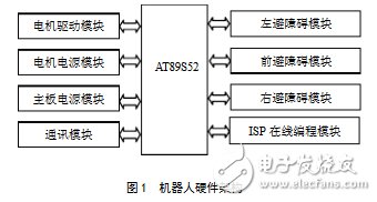
After power-on, the signal of the labyrinth baffle is collected by the sensor to control the lower five digits of the port P0, and the forward/reverse rotation of the left and right motors is realized, so that the robot performs left-turning, right-turning, straight-line advancement and the like, completing the operation in the maze. The journey from the entrance to the exit.
3 system interface circuit design
3.1 Microcontroller Module
The AT89S52 is a low-power, high-performance CMOS 8-bit MCU with an 8KB ISP that can be erased and erased 1000 times of Flash read-only program memory. The device is fabricated using high-density, non-volatile memory technology and is compatible with standard MCS- The 51-instruction system and the 80C51 pin structure integrate a general-purpose 8-bit central processing unit and ISP Flash memory unit to provide a cost-effective solution for many embedded control applications.
AT89S52 has 40 pins, 8KB Flash program memory, 256B RAM, 32 external bidirectional input/output ports, 5 interrupt priority levels, 2 layers interrupt nesting, 2 16-bit programmable timing counters, 2 A full-duplex serial communication port, watchdog (WDT) circuit, on-chip clock oscillator, etc.
In the development process, the development board is used to facilitate the debugging of the program and the testing of the whole machine. After the system debugging is completed, the single chip microcomputer is removed from the development board and installed in the single chip holder of the robot system board, because the robot in the design needs The completed task is relatively simple, so the crystal oscillator and the reset circuit are retained only in the single-chip microcomputer system of the robot system board, and redundant circuits such as the JTAG programming port are eliminated.
3.2 Sensor module
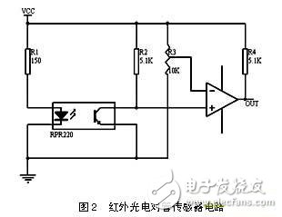
The working principle of the photoelectric sensor is that the infrared emitting tube of the sensor emits infrared light, and the receiving tube counts according to the intensity of the reflected infrared light, so the surface of the detected component or object must have black and white parts for absorbing and reflecting infrared light. In this way, the receiving tube can be in the effective cut-off and saturation area for counting purposes. The detection and adjustment circuit of the sensor is shown in Figure 2. R3 in the figure is used to adjust the threshold voltage of the comparator. Observed by the oscilloscope, the output waveform is quite regular and can be directly used by the MCU for verification, and the voltage drop of the battery that is verified to supply power to this circuit is small. The infrared photoelectric sensor is connected to the P0.5, P0.6 and P0.7 ports of the AT89S52 through the interface of the main board P8, P9 and P10. P0.5 = 0, indicating that there is an obstacle in front; P0.6 = 0, indicating that there is an obstacle on the left; P0.7 = 0, indicating that there is an obstacle on the right.
3.3 DC motor drive circuit and power module
The DC motor is connected to the drive module of the main board through the P5 interface of the main board. In this paper, L298 is used as the driving chip of the motor. The four pins 5, 7, 10 and 12 of L298 are connected to the single-chip microcomputer. The programming of the single-chip microcomputer can realize the functions of the two groups of DC motors. Since the voltage of the single chip microcomputer is about 4.8V, the VFM step-up power supply chip is used to provide a voltage of about 5V for the single chip microcomputer and the peripheral circuit.
4 software design module
4.1 Software Development Environment and Search Algorithm
This article uses Keil U Version2 as the development environment of the system, and uses C language and assembly language mixed programming in programming. In software algorithms, considering the space-time efficiency of the depth-first search algorithm is proportional to the complexity of the maze terrain, that is, the more complicated the maze, the longer the search exit time. This article uses a labyrinth path search strategy called the left-hand (or right-hand) rule, which means that you can find the exit along the left (or right) wall in the labyrinth.
Compared with the depth-first search method, the space occupation of the left-hand (or right-hand) rule has nothing to do with the complexity of the maze. The selection of the robot search path is only related to the current node, and no backtracking is required. At the same time, the manufacturing precision of the hardware is not high, and it is not necessary to accurately control the moving distance and moving direction of the robot, which is convenient for the drive design. In order to facilitate the implementation of the algorithm, this paper sets the following constraints:
1. In the algorithm, no matter how complicated the maze terrain is, it consists of seven basic terrains: straight line, dead end, T-shaped, cross, corner and end point.
2. According to the number of branches, the branching mouth is divided into two mouths and three mouths (generally there are no four mouths), and the roads in front of the branching port are called the first road, the second road, and the third road in the order from right to left. Only the cross type). There are three different forms of Erqi Road. The first one is a winding road to the right of the forward route (the right road is called the first road, the front is called the second road); the second is a road to the left of the forward route. The front is called the first road, the left road is called the second road); the third is the T-junction (the right road is called the first road, and the left road is called the second road). For these three cases, the program corresponding to the algorithm consists of the main program, the straight line subroutine, the left rotor program, the right rotor program, and the syndrome subroutine. The main program functions as a guide and decision maker, determining when the robot should do what. Other functions of the robot are implemented by calling specific subroutines.
4.2 Algorithm Flowchart Description
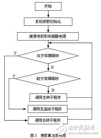
The flow of the maze search algorithm used in this paper is shown in Figure 3. After the motor and sensor power are turned on, the MCU determines the forward and reverse rotation of the motor based on the value detected by the sensor under the control of the program. When P0.7=1, it means there is no obstacle on the left side. According to the “right hand†traversal algorithm, the robot will call the right rotor program; when P0.7=0 and P0.5=0, the robot will call the left rotor. Program; otherwise the robot advances straight, so repeatedly detects and adjusts the robot's motion until the robot moves out of the maze.
5 Conclusions and innovations
In this paper, the hardware architecture of embedded intelligent tracing robot based on AT89S52 is discussed. The left-hand (or right-hand) rule is used for tracing robot walking route search. The photoelectric sensor module based on AT89S52, DC motor drive module and power supply are mainly discussed. The circuit implementation technology of the module, etc., after repeated tests, the robot can intelligently complete the tracing task from the entrance of the labyrinth to the exit without any external force under the control of the software. The innovation lies in the automatic sensing of obstacles by photoelectric sensors, and the use of software to control the left/right rotation of the robot and the straight line walking. It is an attempt to detect complex paths, especially suitable for environmental path detection that cannot be reached by humans. The system cost is low and the reliability is high. It is responsive and has certain reference value for the design and development of smart toys.
High definition LED displays or HD Led screen also called Small pixel pitch Led Display Screens represents the latest and
top technology of Led Display industrial, they are widely used in high-end
conference
rooms, TV studios, the government mansion, etc. With 400mm*300mm cabinet
size, it is very easy to get 16:9 or 4:3 display ratio. As the 400*300mm cabinet is light weight and has high precision in cabinet size.
HD Led screen
HD LED Video Wall ,HD LED Video Wall, indoor LED Display, Indoor LED screen
Shenzhen Priva Tech Co., Ltd. , https://www.privaled.com