Design of wireless data acquisition using ATmega128
In an increasingly market-oriented power environment, power companies must improve service quality to remain competitive. At present, in some areas of China, the automation of distribution network is low, and the work efficiency of personnel is low. According to this demand, a wireless data transmission system is designed. The entire wireless data communication system is based on the point-to-multipoint network structure of RS-485 serial communication. Each station of the digital transmission radio is provided with one station, which is respectively connected to the data collection workstation of the main station and the RTU / FTU of the substation, etc. for polling communication. The operation data report of each substation and the downlink transmission of the control command of the data acquisition workstation are completed by wireless means.
1 Design idea 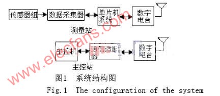
The data acquisition unit uses the advanced ATmega128 embedded single-chip microcomputer as the core component, and uses the RS-485 communication interface to communicate with the control system. The measuring station mainly converts the captured field signal into digital signal after sampling, quantization and encoding by the converter ADC, and transmits it to the microprocessor, receiving the remote control command and sending data; the main job of the main control station is to send the remote control command and receive data Information, data processing and data management. The whole system has a simple structure and high reliability. see picture 1.
1.1 High-speed analog-to-digital conversion chip TLC5510
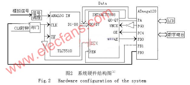
The A / D conversion of this system uses TLC5510 analog-to-digital conversion chip. TLC5510 analog-to-digital conversion chip is TI's 8-bit A / D converter. It is a high-speed, low-power and internal sample and hold circuit. Its data acquisition sequence is to convert data when CLK is high, and output valid data when CLK is low. When reading data from A / D, as long as  Keep it low, when When it is high, D1-D8 are in high impedance state. See Figure 2.
1.2 Interface circuit design and process of data acquisition system
The FIFO chip SN74ACT7808 is a 2048-byte × 9-bit dual-port memory that can implement first-in, first-out asynchronous read and write operations. The read and write operations automatically access consecutive storage units in the memory. The order of the data read from the FIFO is the same as the order of writing, and the order of the addresses has been pre-defined internally. The read and write operations to the FIFO are only controlled by the read and write signals, and no additional address information is required. This makes the control circuit of the FIFO very simple: when reading data, as long as OE remains high and causes UNCK to generate a rising edge; writing data as long as LDCK generates a rising edge.
Because it is high-speed data acquisition, the speed of single chip microcomputer is far from A / D, so we need to design a circuit to automatically complete the data acquisition and storage, see Figure 2. The PB0 pin of the microcontroller is connected to the external CLK clock through the AND gate, so that the microcontroller can control the sampling of A / D. Sampling is performed when PB0 is at a high level. When the PB0 pin is at a low level, there is no pulse in CLK of A / D, and sampling stops. When the data stored in the FIFO is almost full, an interrupt signal is given to the microcontroller. After receiving the interrupt signal, the microcontroller sets PB0 to low level to stop sampling, and then reads the data from the FIFO. Because the PG0 pin of the single-chip microcomputer is connected to the UNCK of the FIFO after the inverter, and the PC4 pin is connected to the OE of the FIFO, its effective address only needs to keep the PC4 pin high. After the data processing is completed, sampling is continued, so repeated, periodic sampling is completed [2].
2 Serial communication between embedded microcontroller ATmega128 and digital radio
ATmega128 is an 8-bit low-power CMOS microprocessor based on AVR RISC structure. The data throughput rate of ATmega128 is up to 1 MIPS / MHz, which can reduce the contradiction between power consumption and processing speed of the system. 8-channel 10-bit ADC (with optional programmable gain), programmable watchdog timer with on-chip oscillator, SPI serial port, asynchronous serial port and JTAG test interface (this interface can also be used for On-chip debugging), and six power-saving modes that can be selected by software.
2.1 Serial communication method of ATmega128 Serial communication baud rate: 9600bps, sending and receiving methods: one start bit, 8 data bits, odd parity, 1 stop bit. UARTO initialization can be set in the ICC AVR, and the Builder automatically generates the interrupt service subroutine and population address, just add the person processing code in the service subroutine.
// UARTO iniTIalisaTIon
// desired baud rate: 9600
// char size: 8bit
// parity: Disabled
void uart0_init (void)
{
UCSR0A = 0x00;
UCSR0B = 0x98; // Reception completed interrupt is allowed, sending data is allowed.
UCSR0C = 0x06; // The length of the character sent and received is 8 bits.
UBRR0H = 0x00;
}
When receiving data, the MCU sets a flag, assuming that the first "*" character is received, the flag is set to 1, that the communication is normal and can receive data. When receiving data, it is judged whether the reception completion message is received; if yes, the flag is cleared, making the data received next time invalid, until "*" is received again, the flag is set to 1. When the flag is 1, determine whether the message is received (character value is equal to 8); yes, clear the last received character to 0; otherwise, save the received data in the receive buffer. After performing the operation, the received characters are finally sent back to the computer. The single-chip microcomputer communication flow chart is shown in Figure 3.

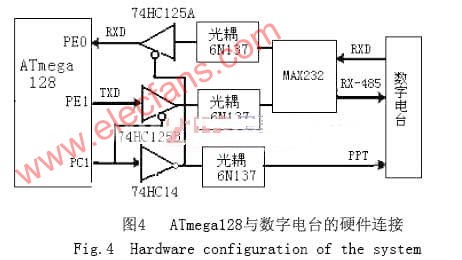
2.2 Hardware connection between ATmega128 and digital radio station Communication protocol of digital radio station with single chip computer and terminal host computer: standard serial RS485 interface, communication frame format-1 start bit, 8 data bits, 1 programmable data Bit, 1 stop bit, baud rate 9600bps. It is recommended to use the narrow-band wireless data transmission station MDS SCADA, which is specially used in power automation. This radio adopts industrial-grade cast aluminum package, which can improve electromagnetic interference, strong diffraction ability, provides standard RS-485 interface, and the system responds quickly.
The system uses asynchronous serial communication. Use the serial port of the single-chip computer to connect with the RS-485 data port of the digital radio station. The normal state of the radio station is the receiving state (PPT = 0, receiving state; PPT = 1, sending state). The single chip microcomputer controls the transceiver of the radio station through the tristate buffer gate 74HC125 and the non-gate 74HC14 with a control terminal. When receiving, PC1 = 1, PC1 is reversed and photoelectrically isolated by 74HC14, so that the radio PPT pin is low, and it is set to the receiving state; when transmitting, PC1 = 0, reversed and photoelectrically isolated by 74HC14, makes the radio PPT The pin is high level, set it to the transmitting state; at the same time 74HC125A is cut off, 74HC125B is turned on, the data is output from the TXD pin of the single chip microcomputer, through 74HC125B buffer gate, photoelectric isolation, MAX232 level conversion, the data is sent out through the radio TXD port. The specific hardware connection is shown in Figure 4.
3 Conclusion The country's rural power grid transformation has greatly improved the power supply capacity of the distribution network. However, with the development of social economy, higher requirements have been put on the power sector. Combined with the actual situation of the power grid, for areas where high real-time performance and high distribution quality requirements are taught, after the wireless data transmission system is built and used, the operation results show that the system works stably and reliably. Compared with the wired network, this system has low network construction costs, It has the advantages of short construction period, small maintenance, strong disaster resistance, no need for line inspection and maintenance, and easy data transmission. Because ATmega128 is used in the data acquisition system, its development speed has been greatly improved compared with the past. This efficient and flexible embedded is being widely used in the field of industrial control and has broad prospects.
4 Innovative points of the author of this article: 1. This system uses a variety of advanced technologies, high-performance single-chip system technology, wireless transmission technology, computer remote control technology, etc. 2. This system has outstanding advantages such as high degree of automation, good system reliability and stability, and high data collection accuracy. 3. Because the system and the host computer system can easily communicate and transfer data, the data recorded in the test can be saved in the computer database, which is helpful to realize the network, digitization and informationization of power dispatching.
120W Solar Street Lights,120W Outdoor Solar Street Light,120W Waterproof Solar Street Light,120W Solar Led Street Light
Yangzhou Bright Solar Solutions Co., Ltd. , https://www.solarlights.pl