Capacitive proximity sensors are commonly used to detect the presence of a user at a close proximity of the sensor. By detecting, when a user is sensed, we can choose backlight illumination to highlight a particular button or wake up the system from a low-power mode of operation. Specifically for automotive applications, when the capacitive proximity sensor senses that the user is inside the vehicle, it will turn on the cabin light or activate the keyless door unlocking system. In addition to the presence or absence of a user near the inductive sensor, we can also identify simple gestures in the air by appropriately placing multiple proximity sensors. The data for all sensors can be combined to map out the gestures of the user in the vicinity of the sensor. These gestures can be used to provide input to the system, including controlling the media player, navigating the map, or browsing playlists.
This article refers to the address: http://
We can place multiple proximity sensors as appropriate to leave an appropriate distance between each other. When the hand passes over the sensor, the time at which each sensor detects the hand movement is different. The relative detection order and detection duration of different sensors can be used to analyze the direction and speed of hand movement. Gestures can be as simple as drawing a line from left to right above these sensors; it can be complicated, including drawing a circle in your hand by hand. In this article, we will analyze how to use different modes of multiple sensors for simple gesture recognition and how to implement more complex gestures.
Below we analyze the four capacitive proximity sensors placed around the car infotainment system shown in Figure 1.
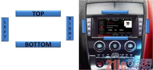
Figure 1. The image on the right shows a capacitive proximity sensor placed around the car infotainment system. The left icon shows its position.
The placement of the sensor should be just right, ensuring that the sensor is triggered in sequence to make a gesture above the sensor panel (different sequences produce different effects). We will confirm the trigger sequence of the sensor. If the order matches a preset sequence, the corresponding operation instruction for this gesture is issued. We will use the sensor placement mode shown in Figure 1 as a reference to introduce you to the gesture operations discussed in this article.
Imagine a simple gesture of drawing a straight line above the sensor from left to right, as shown in Figure 2(a). When the hand sweeps the sensor from left to right, the left sensor is triggered first as soon as the hand approaches the system. The word "trigger" here means that the sensor detects the presence of an object and cannot be misunderstood as enabling the proximity sensor. Because the system is turned on once the system is turned on, it keeps scanning sense for objects in nearby areas.
?
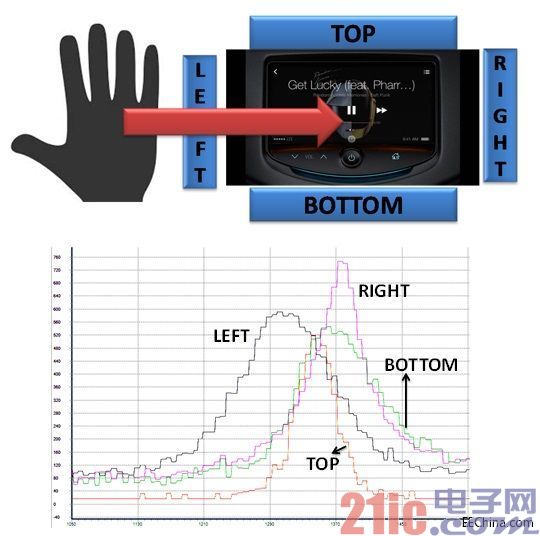
Figure 2. (a hand draws a straight line from left to right in the air; (b) a signal diagram of each sensor when hand-drawing a line
When the hand passes over the console, the top and bottom sensors are triggered while the left sensor remains triggered. When the hand continues to swipe to the right, the right sensor is triggered. The left sensor stops sensing after the hand leaves its detection range. When the hand passes over the right sensor, the top and bottom sensors no longer detect the presence of the hand. When the hand is further away, the right sensor will also stop sensing. The order in which the sensors are triggered will be one of the following, depending on the position of the hand and the sensitivity of each sensor:
Right → top → bottom → left
Right → bottom → top → left
Right → bottom → left
Right → top → left
All of the above sensor activation sequences correspond to gestures (left → right). This example uses PSoC to implement a capacitive proximity sensor. Capacitance-to-digital converters in PSoC (also known as Capsense Sigma Delta) can be used to measure capacitance. The output of the CSD module is the raw count. The larger the raw count, the higher the capacitance sensed by the sensor. The closer the hand is to the proximity sensor, the greater the capacitance of the sensor.
When the raw count of the sensor exceeds a certain threshold of the base value, the sensor is triggered by the presence of an object detected in its vicinity. When the hand draws a straight line from left to right (as shown in Figure 2(a)), the raw count graphs of the four sensors are shown in Figure 2(b). This figure confirms the activation sequence of the above sensors. If the hand moves in the opposite direction, that is, the gesture operation (right → left), the sensor trigger sequence is opposite to the activation sequence of the left and right sensors described above. That is to say, the sensor activation sequence corresponding to the (right→left) gesture at this time is one of the following:
Right → top → bottom → left
Right → bottom → top → left
Right → bottom → left
Right → top → left
The two gestures described above are the movement of the hand in the horizontal direction. Similarly, the hand can also draw a straight line in the vertical direction, that is, (top → bottom) or (bottom → top) gestures, depending on the direction in which the hand moves.
The gestures of (up to down) or (down → up) can be associated with simple operations such as scrolling up and down menus or track lists, as shown in Figure 3.

Figure 3. Scrolling the menu by drawing a straight line approach gesture in the vertical direction of the hand
The gestures (left→right) and (right→left) can be associated with a song-changing or changing operation of the music player application. By placing a proximity sensor (as shown in Figure 4), the same gesture can also be used to switch the lights inside the cabin instead of pressing a button.
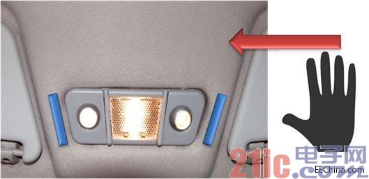
Figure 4. Controlling the cabin ceiling lights by hand-drawing a straight line
The (top to bottom) gesture is similar to the up/down button press action. However, while holding down the up (down) button, the screen scrolls up (down) until the button is released. In other words, as long as the button is pressed, this action is "sticky." To make the gesture operation completely replace the button operation, the gesture operation should also support this "stickiness" function. We will modify the gesture as follows to meet this requirement. As the hand moves from the top sensor to the bottom sensor, the system decodes this into a (top-to-bottom) gesture as soon as the hand passes over the bottom sensor. We change the gesture and when we press the gesture sequence to reach the last sensor (here the bottom sensor), we issue a command to scroll down. And as long as the hand remains above the bottom sensor, it will repeatedly issue a command to scroll down. Wait until you scroll to the menu item you want to find, and then move the hand down and away from the bottom sensor sensing range, and the command to scroll down will stop. In other words, to make the gesture operation "sticky", the hand can't complete the swipe from top to bottom at once, but pause at the last sensor to find the desired item and then leave the sensor. range. As long as the hand stops in the sensing range of the sensor, the command will be issued all the time.
Figure 5 shows the raw count map of the top and bottom sensors for the (top to bottom) viscous gesture. After the top sensor stops sensing the gesture, the bottom sensor will remain in a longer trigger state, indicating that the sensor's sensing range at the bottom sensor has stopped, rather than continuing to draw directly. When sending a sticky command, we check to see if the top sensor is triggered first and then whether the bottom sensor is triggered. At this time, the top sensor no longer senses the gesture operation, and the bottom sensor can still sense that the hand is nearby. When the hand stays within the range of the bottom sensor for more than a certain time threshold, the sticking command will always be issued as long as the bottom sensor senses that the hand is nearby. Similarly, we can also modify other gestures to achieve the "stickiness" feature, which allows the gesture operation to completely replace the up and down button functions.
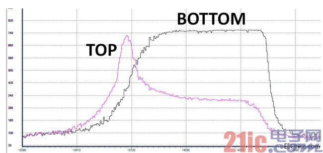
Figure 5. Top and bottom sensor signal diagrams for the top-bottom sticky gesture. The bottom sensor's signal stays on, indicating a "sticky" gesture operation.
Next, let's look at a slightly more complicated gesture. Imagine a scene in which the hand is circled in the air above the sensor panel, as shown in Figure 6.
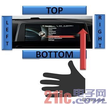
Figure 6. Geometry operation
The hand can draw a circle above the other sensor from the sensing position of either sensor, either clockwise or counterclockwise. The circle is completed when the hand draws the circle back to the starting sensor, and the circle is exited after the hand is removed. For example, the hand can begin to circle clockwise above the right sensor, sequentially through the bottom, left and top sensors, and finally back to the right sensor, then exit the circle process. Figure 7 also shows the raw count map of the sensor. In the same way, the direction of the hand's movement is reversed to complete the counterclockwise circle. In addition, the sensor firing sequence also counts multiple circle operations.

Figure 7. Sensor raw count graph for clockwise circle gesture operation
The circle gesture is similar to the action of turning the knob, and can be associated with an operation command such as a music player volume adjustment or a map browsing zoom.
In this article, we discussed how to use a capacitive proximity sensor for simple proximity gesture detection. Using the same principles, we can build more complex gestures, including drawing pictures in the air with both hands. However, whether this gesture operation can be successfully detected depends on the sensor mode layout we choose is not good enough. It is important to choose the appropriate mode layout, not only to provide proper tolerance for hand movements of various gesture operations, but also to determine the trigger sequence of the sensor.
1.5"~2" speaker (40~50mm)
1)1.5" Speaker 40Mm Speaker
2)1.75" Speaker 44Mm Speaker
3)1.8" Speaker 45Mm Speaker
4)1.9" Speaker 48Mm Speaker
5)2" speaker 50mm speaker


FAQ
Q1. What is the MOQ?
XDEC: 2000pcs for one model.
Q2. What is the delivery lead time?
XDEC: 15 days for normal orders, 10 days for urgent orders.
Q3. What are the payment methods?
XDEC: T/T, PayPal, Western Union, Money Gram.
Q4. Can you offer samples for testing?
XDEC: Yes, we offer free samples.
Q5. How soon can you send samples?
XDEC: We can send samples in 3-5 days.
1.5"~2" Speaker 40~50mm
1.5" Speaker 40Mm Speaker,1.75" Speaker 44Mm Speaker,1.8" Speaker 45Mm Speaker,1.9" Speaker 48Mm Speaker
Shenzhen Xuanda Electronics Co., Ltd. , https://www.xdecspeaker.com