Vehicle exhaust gas detection system based on virtual instrument technology
Abstract: In order to monitor and prevent environmental pollution caused by vehicle exhaust emissions, this paper introduces a vehicle exhaust gas detection system based on virtual instrument technology. Firstly, the structure and working principle of the detection system are introduced. A graphical programming language LabVIEw8.2 developed by NI Company of USA is proposed as the development environment. The VS5067-5 produced by Siemens AG of Germany is used as the exhaust gas analyzer for automobile exhaust gas detection. The method of system design. In particular, the LabVIEW 8.2 implementation of the Industrial Computer and the VS5067-5 serial communication program is described in detail. The actual test results show that the method is convenient and practical, and has the value of popularization and application.
0 Preface
In recent years, with the rapid development of China's social economy and the continuous improvement of people's living standards, the number of car ownership has increased significantly. While bringing convenience to people's daily lives, cars also bring serious environmental problems. Harmful gases such as CO and HC compounds in automobile exhaust have become the main source of air pollution. Therefore, monitoring and controlling the exhaust pollution of automobiles is an important task to control environmental pollution.
To control the exhaust pollution of motor vehicles, the first thing to do is to do the testing. In China, since 1999, a series of corresponding regulations have been formulated to strictly control the emission of automobile exhaust. In 2005, the new national standard GB 18285-2005 "Ignition Engine Vehicle Exhaust Pollutant Emission Limits and Measurement Methods" was promulgated, except for the measurement method of exhaust pollutants for vehicles under idle and high idle conditions. In addition to the requirements, each type of vehicle exhaust pollutant emission limits are clearly defined.
The main detection parameters of automobile exhaust pollutants are: CO (carbon monoxide), HC (hydrocarbon), CO2 (carbon dioxide), O2 (oxygen), NO (nitrogen monoxide) and the like.
1 Detection system composition
The hardware structure of the automobile exhaust gas detection system based on virtual instrument technology is shown in Figure 1.
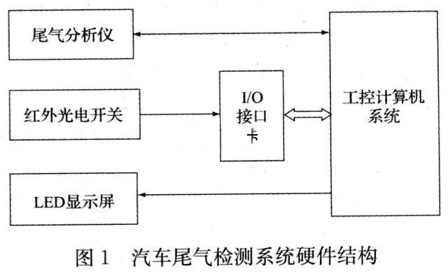
The detection system is mainly composed of exhaust gas analyzer, I/O interface card, infrared photoelectric switch, LED display and industrial computer. The exhaust gas analyzer adopts the VS5067-5 automobile exhaust gas analyzer of Siemens of Germany. The core component of the instrument is the infrared optical sensor of Siemens. The working principle is based on the characteristic absorption bands and characteristic frequencies of different gases. The spectral band near the frequency produces strong absorption. According to the intensity of the infrared absorption of the gas, the composition and content of the automobile exhaust are detected and analyzed. The instrument can detect the concentration of five kinds of gases such as CO, HC, CO2, O2 and NO in the exhaust of the automobile and the working parameters of the engine oil temperature and speed. The measurement data is displayed by the liquid crystal display on the instrument panel and is equipped with a standard RS232 string. The line interface is connected to the industrial computer, and the measurement command can be received through the serial port and the test result can be output.
The extended I/O interface card on the industrial computer is mainly used to receive the on/off status of the infrared photoelectric switch to determine whether the vehicle being inspected is in place. The infrared photoelectric switch adopts the Oulong E3JK-5M type, and its infrared radiation distance is 5m. The infrared emitting photocell and the infrared receiving photocell are respectively installed on both sides of the automobile detecting line. When the infrared transmitting tube is not blocked, the receiving photocell is normally closed. When the inspected vehicle travels to the detecting station to block the infrared emitting photocell, the receiving photocell is in an open state, and the receiving photocell is opened and closed. Indicates whether the vehicle is in place.
The LED display is used to display the inspection process information and test results. The pilot and the exhaust gas inspector can perform the corresponding operations under the guidance of the LED display.
The working process of the exhaust gas detection system is: when the vehicle is registered for online detection, the industrial control computer issues a vehicle incoming message, prompting the inspected vehicle to enter the inspection station. When the industrial computer detects that the receiving photocell is in an open state, it indicates that the vehicle is in place, and exhaust gas detection can be started. The testing procedure will be carried out in accordance with the measurement method specified in the national standard GB18285-2005. During the detection process, the exhaust gas inspector inserts the sampling probe into the exhaust pipe of the vehicle to be inspected according to the indication of the LED display, and connects the speed measuring clamp to the relevant part of the engine according to the requirements; the exhaust gas analyzer receives the command of the industrial computer from the serial port, The exhaust pollutants are collected; the driver guides the vehicle to enter the rated speed, high idle speed, idle speed, etc. according to the indication information of the LED display screen, and completes the exhaust gas emission measurement according to the detection program with the exhaust gas analyzer.
2 detection software design
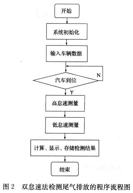
Software is the key to virtual instrumentation. Design a virtual instrument system. After the hardware platform is determined, different software modules can be designed to achieve different functions. The application software for the automotive exhaust gas detection system was developed using NI's graphical programming language LabVIEW 8.2. The flow chart of the process of detecting exhaust emissions by double idle method is shown in Fig. 2.
The execution process of the double idle method exhaust gas detection program is as follows: firstly, the basic information of the inspected vehicle is input on the main program interface, and then the LED display screen is used to prompt the inspected vehicle to enter the detecting station, and the state of the infrared receiving photocell is read to determine that the vehicle is in place. Happening. If the vehicle is in place, the exhaust emission test is performed according to the double idle speed measurement method specified by the national standard, and the test data is input by the serial port. Finally calculate the data, display and store the test results. For the sake of simplicity, the raw data collected can be output in the form of a graph.
In the design of the test program, since the industrial computer and the exhaust gas analyzer transmit measurement commands and measurement data through the serial port, the serial communication program is one of the most critical modules in the detection software. In LabVIEW 8.2, you can use the VISA module to write serial communication programs, so that you can get rid of the cumbersome underlying commands and easily realize the communication between the industrial computer and the instrument.
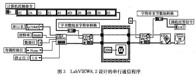
The communication parameters of VS5067-5 automobile exhaust gas analyzer are: 9600 baud rate, 8 data bits, no parity, 1 stop bit, communication commands include: computer control, CAL, measurement, read data, end measurement, manual operation Etc., the command format is a multi-byte ASCII code format. For example, the "computer control" command is: 02H, *, S, R, E, M, 20H, K, O, 03H, that is, 10 bytes of ASCII code. . Similarly, the response signal of the instrument is also a multi-byte ASCII code. For example, the response signal corresponding to the "computer control" command is 9 bytes of ASCII code, namely: 02H, *, S, R, E, M, 20H, 0,03H. That is to say, the serial data between the industrial computer and the exhaust gas analyzer is multi-byte ASCII code information. Since it is convenient to use hexadecimal notation for general ASCII code in program development, there is a problem of data type conversion between serial transmission and reception of data. In LabVIEW 8.2, the conversion of ASCII code and hexadecimal data can be easily implemented by two functions: "byte array to string conversion" and "string to byte array conversion". Taking the "Computer Control" command as an example, the serial communication program designed by LabVIEW 8.2 is shown in Figure 3.
The serial communication program is written as follows:
1) Serial port initialization
According to the VS5067-5 automobile exhaust gas analyzer communication protocol, use the "VISA configuration serial port" function in the [Data Communication] → [Protocol] → [Serial Port] sub-palette of the LabVIEW 8.2 function palette to initialize the serial port to a baud rate of 9600 bps. The data bit is 8 bits, 1 stop bit, no parity bit, and the COM1 port of the industrial computer is selected.
2) Send measurement command
When the industrial computer sends a measurement command to the exhaust gas analyzer, it can be sent using the “VISA Write†function. Since the command of the exhaust gas analyzer is in multi-byte ASCII format, it is necessary to build the command group into an array and then use the "byte array to string conversion" function to convert the array into a string. Figure 3 shows the transmission of the "Computer Control" command. The hexadecimal representation of the "Computer Control" command is: 02H, 2AH, 53H, 52H, 45H, 4DH, 20H, 4BH, 30H, 03H.
3) Receive response signal
When the exhaust gas analyzer receives the command from the industrial computer, it will return a response signal. In the program design, the "VISA Read" function can be used to receive the response signal from the instrument, and then use the "string to byte array conversion" function. Convert received ASCII data to hexadecimal data. For example, when the instrument receives the "computer control" command, the response signal returned is expressed in hexadecimal notation: 02H, 2AH, 53H, 52H, 45H, 4DH, 20H, 30H, 03H. If the industrial computer sends a “read data†command to the instrument, the response signal returned by the instrument includes HC, CO, CO2, O2, NO, and the detection data such as the rotational speed, oil temperature, and λ (excess air ratio).
4) Close the serial port
When the industrial computer wants to stop the exhaust gas detection, you can use the "VISA shutdown" function to close the serial port and release the resources occupied by LabVIEW.
3 Experimental results
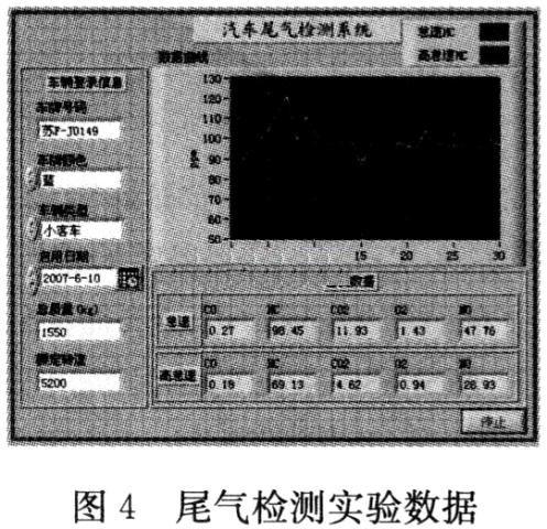
We conducted exhaust gas detection experiments for multiple vehicles on the automotive exhaust gas detection system developed based on LabVIEW 8.2. During the experiment, different car types were selected and a large amount of experimental data was obtained. Figure 4 shows the measurement results of a small passenger car. The figure shows the raw data curve of idle and high idle HC, and the data curve showing CO or other parameters can also be selected.
4 Conclusion
This system uses LabVIEW8.2 as the development platform, which can conveniently detect the concentration of automobile exhaust pollutants such as HC, CO, CO2, O2 and NO. The experimental results show that the system has high stability and measurement accuracy. In addition, by configuring the network card on the industrial computer, the network detection of the vehicle exhaust can be realized, so that the automobile exhaust gas detection system can be conveniently applied to the new vehicle research and development experiment, the factory inspection of the new vehicle, and the vehicle comprehensive inspection of the vehicle on the road. In the performance test line, the application prospect is very broad.
1. Display, touch screen, PC system integration slim design
2. Using the projected capacitive screen, supports 10 point touch, handwriting and multi-point gesture;;
3. Pure flat , Aluminum alloy + sheet metal structure ;
4. Flexible configuration, with many options of different RAM/SSD/HDD, supports OS of Android/windows/Linux etc.
5. High safety; Stable performance:
6. Simple installation for embedded/desktop/wall mounting
All In One Pc,All In One Computer,Touch Screen Aio Pc,All In One Touch Pc
Guangzhou TouchWo Electronics Co.,Ltd. , http://www.touchaio.com