At present, biometrics - the application of live fingerprint identification system is increasingly widely used. Veridicon's I-touch semiconductor fingerprint sensor is a 300&TImes; 300 dot matrix, 500 DPI low-power sensor device with integrated temperature sensor and resistor. Sensors thus prevent electronic fraud. The sensor has the advantages of “small size, low cost, low power consumption, high safetyâ€, and the surface of the chip is covered with a protective layer for profit protection, which can effectively prevent wear and corrosion, and thus obtain many developers of fingerprint recognition systems. usage of. However, in the process of developing and using the I-touch fingerprint sensor, the I-touch device has a problem of effective image capturing efficiency, and thus some modifications are needed.
1 Confirmation of valid fingerprint images and problems
When the fingerprint image capture system is working, only the images captured twice in succession can determine that the image is a valid image. In actual use, it is often the sensor that starts the scanning process first, and then the subject and the finger are scanned, so at the beginning, it may just scan an incomplete fingerprint image, and wait until the next scan. A complete fingerprint image, so that two different images are obtained, so a third scan must be performed, but when the third scan is not over, the subject stays on the sensor for too long. Impatient, you may take your finger out or move it again, which will make the resulting three images different, so that the sensor will return an invalid image. The final result is that the subject has to rescan the fingerprint.
Since the I-touch fingerprint sensor work start mode has only two settings, one is initiated by the programmer to preset the "Enter" key; the other is automatically continuous after booting. The I-touch fingerprint sensor does not have an inductive device that recognizes and controls whether the subject is operating correctly. Therefore, both of the above startup modes have problems in that the subject's finger is not placed in position at the time of startup, so that an empty scan or an incomplete scan is generated to form an invalid image, which requires multiple operations and affects work efficiency.
2 Improved design for startup and synchronization
2.1 finger and position touch switch
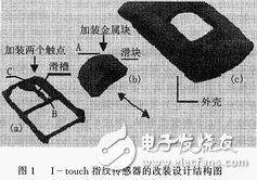
After careful study and repeated experiments, the author installed a finger-in-place switch in the I-touch fingerprint sensor. Only when the finger is fully in place, the system starts to start the fingerprint scanning program, thus effectively solving the work start and the detected finger are not in place. The problem of synchronization. The specific structure is shown in Figure 1. The design is to install two contacts in the I-touch fingerprint sensor. One of the contacts is led out by the MCU pin P1.0 and the other is directly connected to the ground. A metal block is added to point A of the slider to form a touch switch. When working, the finger to be inspected pushes the slider, and moves from the B point of the chute to the C point. When it is fully in place, the two contacts are just turned on, and at the same time, the input P1.0 pin of the single chip is set to a low level. The input signal of the single-chip microcomputer is formed, and the I-touch fingerprint sensor is immediately activated through the interface between the single-chip microcomputer and the PC, and the fingerprint scanning is started.
2.2 Touch switch hardware circuit
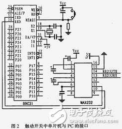
Figure 2 is a hardware circuit diagram of the design of the interface between the microcontroller and the PC in the touch switch. This circuit uses ATML89C51, MAX232 and some peripheral components to form a serial communication circuit.
When the circuit is working, the switch 1 is turned on, and the P1.0 pin changes from the high level to the low level. When the MCU detects that the P1.0 input is low, the “S†signal is transmitted to the serial port of the PC through the MAX232. Let the PC control the fingerprint sensor to perform the scanning process. When the PC wants to collect the fingerprint image, the com2 port sends an “E†signal to the MCU to indicate the end, and P2.0 is set to a low level, and the indicator light is illuminated to indicate to the user that the fingerprint collection is completed. The user can leave at this time.
Simosec Air Insulated Switchgear
Siemens Wl Switchgear,Switchgear Battery Charger,Simosec Air Insulated Switchgear,Secondary Switchgear Refurbishment
Shandong Shunkai electrical equipment co., LTD. , https://www.chinasdsk.com