As the main equipment for high-voltage power grid detection, the current transformer not only provides parameters for the measurement of electric energy, but also provides the basis for relay protection. With the development of national smart grids and UHV grids, traditional electromagnetic current transformers have gradually exposed their fatal defects. For example, insulation is extremely difficult at high voltage levels, and magnetic saturation at higher voltages leads to a decrease in measurement accuracy. In contrast, fiber optic current transformers have many advantages such as strong anti-electromagnetic interference capability, reliable insulation, high measurement accuracy, simple structure and small size, which are the current research hotspots. As a core component of fiber optic current transformers, its detection and control circuitry has a very important impact on current detection accuracy and range.
At present, there are two main schemes for detection and control circuit implementation. One is based on digital signal processing chip (DSP). Due to the faster and faster DSP, DSP has become the first choice for many data processing and signal detection schemes. Timing control is the bottleneck. Because the timing control accuracy and speed directly affect the detection accuracy of the fiber-optic current transformer, the control accuracy of this scheme is limited. The other is the field-programmable gate array (FPGA) and DSP as the core components. Combining the advantages of both, FPGA is used to complete the system timing control. DSP implements various digital signal processing algorithms. Although very high control precision can be obtained, the system structure is relatively complicated and the reliability is degraded. With the development of FPGA technology, FPGAs are not only used for precise timing control, but also for complex digital signal processing functions. In this paper, FPGA is used to realize precise timing control, and a very complex signal processing algorithm is realized. The FPGA is used as the core device to complete the signal detection and control circuit design of the fiber-optic current transformer. The circuit is used to control the current of the fiber-optic current transformer. Testing and calibration. The test results show that the system control accuracy meets the requirements of 0.2 S-level measurement accuracy.
1 All-fiber current transformer signal detection and control principle
All-fiber current sensing technology uses the Faraday effect to achieve current detection. When a bundle of linearly polarized light passes through a substance in a magnetic field, the vibrating surface of the polarized light will rotate to a certain extent, so that the rotation angle can be measured. To obtain information about the magnetic field and the current that generates the magnetic field, wherein the angle of rotation of the vibrating surface can be derived from equation (1):
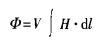
Where: Φ is the magnetic Faraday deflection angle; V is the Verdet constant of the fiber; H is the magnetic field strength; l is the distance between the light and the magnetic field.
The essence of the Faraday effect is magnetically induced circular birefringence, which is explained by the fact that linearly polarized light can be decomposed into two oppositely circularly polarized light (left-handed and right-handed), and the applied magnetic field causes the material to be orthogonally circularly polarized. The difference in refractive index causes their propagation velocity in the material to be no longer uniform. After the two circularly polarized light propagates for a certain distance, a certain phase difference ΔΦs is generated, and the polarization plane of the corresponding linearly polarized light is rotated. By measuring the phase difference, the magnetic field and the current information of the generated magnetic field can be obtained, and the relationship between the phase difference ΔΦs and the Faraday rotation angle Φ has been proved to be ΔΦs=2Φ.
If the optical path is closed around the energization conductor and when the magnetic field H is generated only by the current in the conductor passing through the sensing fiber optic ring, the equation (1) and the amperage loop law can be used:
△Φs=2VNnI(2)
Where: ΔΦs is the magnetically induced Faraday phase difference; V is the Verdet constant of the fiber; N is the number of times the beam surrounds the conductor; n is the number of conductors in the sensing fiber coil; and I is the current passing through the single conductor.
It can be seen that the magnitude of the phase difference caused by the Faraday effect of the two orthogonally circularly polarized lights is proportional to the number of times the beam surrounds the conductor and the total current passing through the sensing fiber optic ring. Since the number of times the beam is around the conductor is known, the magnitude of the current to be measured can be calculated as long as ΔΦs is measured.
2 signal detection and control circuit implementation
The overall block diagram of the signal detection and control circuit is shown in Figure 1. The optical fiber sensing head inputs the optical signal carrying the phase difference information to the photodetector (the phase difference is proportional to the amplitude of the photodetector output signal), and the voltage signal output by the photodetector is first subjected to DC blocking processing, and then amplified and filtered. After that, it is converted into a digital signal by an A/D (analog-to-digital converter), and then sent to an FPGA-based digital signal processing unit. Data demodulation, integration and filtering are performed in the FPGA, and the stepped wave step height is calculated by the staircase wave generation algorithm. Then the step wave and the fixed-cycle modulated square wave are superimposed under the control of the timing control unit, and then controlled by the FPGA. The /A (digital-to-analog converter) converts to form an analog voltage waveform that drives the phase modulator, which completes a closed-loop feedback of the system. In addition, the stepped wave step height data is digitally filtered and transmitted to the control computer by the asynchronous serial transceiver (UART). Since the height of the step is related to the current to be measured, the upper layer software can obtain the measured current by simple processing. . The timing control of the whole system is completed in the FPGA, and the timing control of square wave modulation, A/D acquisition, digital staircase wave feedback, data output, etc. is required to have a strict synchronization relationship.
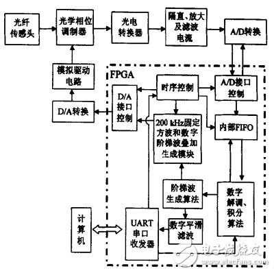
Figure 1 signal detection and control circuit block diagram
According to the data in Table 1, the error curve in the full scale range can be obtained, as shown in Fig. 4. It can be seen that the measured error within the full scale range meets the requirements of 0.2 S-level measurement accuracy. That is, the designed circuit completes the closed-loop control and test data demodulation of the fiber sensing head.
In this paper, the closed-loop detection control circuit for all-fiber current transformers is preliminarily studied. Based on single-chip FPGA, signal acquisition, data output, and computer communication control and data demodulation, integral filtering, staircase wave generation and other algorithms are completed. Fiber optic current transformer sensor head output signal detection and closed loop control. The control circuit has the characteristics of simple structure, high integration, fast closed-loop control speed and high control precision, which lays a foundation for the development of all-fiber current transformers that meet the requirements of power grid testing. In addition, the prototype of all-fiber current transformer developed based on the control circuit has been tested to achieve 0.2 S-level measurement accuracy in the range of rated currents from 100 A to 4000 A, and initially meets the measurement accuracy of the current transformer for the power grid. Requirements.
2.1 preamplifier and filter circuit
Since the output signal of the photodetector is relatively weak and contains higher frequency noise information, it needs to be amplified and filtered before the subsequent A/D conversion can be quantized into a digital signal. Therefore, the preamplifier and filter circuit affects the subsequent measurement accuracy by amplifying the useful signal and suppressing the noise. The preamplifier circuit uses the differential op amp AD8130, which has a very high common-mode rejection ratio and is especially suitable for applications requiring low noise, low harmonic distortion, and high common-mode rejection ratio in weak signal amplification. The frequency of the AC effective square wave signal output by the photodetector is about 200 kHz. To ensure that the square wave signal has no distortion through the back end filter circuit, the high frequency cutoff frequency of the filter circuit must be 20 times without the square wave fundamental frequency signal. Harmonic design, in order to avoid high-frequency noise into the back-end sampling and quantization module, the high-frequency cutoff bandwidth can not be too wide, this design uses a 4 MHz bandwidth π-type filter to achieve front-end filtering.
2.2 data acquisition circuit
In order to ensure the measurement accuracy of 0.2S (ie, two thousandths), the A/D conversion digits need to reach more than 10 digits. In addition, in order to ensure the sampling frequency of the high-low level of each period of the 200 kHz square wave signal, it is possible to increase the sampling precision by accumulating and averaging, and it is necessary to average the square wave high and low levels after each sampling for more than 20 times in each period. This requires the analog-to-digital converter sampling rate to be greater than 8 MS/s. The design retains a certain margin with an analog-to-digital converter AD9248 with a quantized bit size of 14 bits and a sampling rate of 20 MS/s. The chip uses multiple stages with Output differential correction logic differential pipeline structure, integrated two high-performance sample-and-hold amplifiers and a reference voltage source, only need to provide control clock, its conversion data automatically appears in the data port after 7 clocks, for precision timing control occasions Very convenient.
ALL SIZE CANDLES AND WEIGHT WE CAN SUPPLY TO AFRICA .IT MADE OF PARAFFIN WAX AND STEARIC ACID , 10-95G White Candle SELL VERY WELL FOR Africa , Lerget White Candle , such as 65g 68g sell very well for Angola .PURE WHITE COLOR CANDLE ,SNOW WHITE CANDLE ,OFF WHITE CANDLE .
AND EVERY COLOR CANDLES WE CAN DO .Peolpe usually use for Lighting ,wedding ,festival , it early to take and Pure White Candle is long time burning . White Color Church Candles looks smooth ,smokeless, stick .WE CAN SUPPLY CANDLES BRAND DESIGN ,CARTON DESIGN
10-95Gram White Candle,Large White Candle,Pure White Candle,White Color Church Candles
Shijiazhuang Zhongya Candle Co,. Ltd. , https://www.zycandlefactory.com