introduction
At present, large bases (such as warehouses) are very concerned about the temperature and humidity parameters inside their space, because this is directly related to whether the equipment stored therein can be preserved without corrosion and intact. Therefore, it is necessary to be able to automatically measure the temperature and humidity in the space and turn on the fan to control the temperature and humidity when needed. This paper proposes a distributed system combined with Modbus protocol to collect data with high stability and high reliability. At the same time, the powerful function of ACCESS is used to analyze and process data and issue fan commands on the PC to realize automatic measurement and control of temperature and humidity.
1 system composition
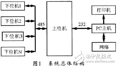
The temperature and humidity measurement and control system belongs to the sensor space stereoscopic distributed measurement and control system, adopts PC host and a host computer, and several lower computers to realize master-slave communication, and uses RS485 communication mode and adopts Modbus protocol to form industrial grade 485. Network, then add fans, printers, etc. Thus, a complete system is constructed to monitor and control the temperature and humidity parameters of the base. The lower computer uses a one-wire bus (12wireinter2face) temperature sensor to accurately collect the temperature and humidity signals from the shtll humidity sensor, and uses the PIC16 microcontroller to send the processed signals to the host computer through the RS-485 bus. The upper computer adopts the central control unit of AT89S52, which can perform data processing and data storage, and can realize data interaction with PC, and then drive the fan to control the on/off of the switch through the network. Figure 1 shows the overall block diagram of the system.
2 Modbus protocol
The Modbus protocol is suitable for half-duplex RS-485 buses. There may be one master and multiple slaves on the bus, each of which assigns a unique address. When working, the command-response communication method is adopted. Each command frame corresponds to a response frame. The host can issue a command frame to the slave to be accessed, and then respond by the slave with the matching address, and then send the response to the host. The response frame corresponding to the command frame; the slave whose address does not match does not respond to the command frame. This kind of question-and-answer communication method can greatly improve the correctness of data transmission.
The standard Modbus protocol defines a number of function codes for command frames. Different function codes require different responses from the slave. The Modbus protocol is divided into an ASC code mode and an RTU mode. Generally, the application wants to increase the amount of data transmission as much as possible in a short period of time. Therefore, the RTU method is mostly used.
Regardless of the command frame or the response frame, the start and end of the message frame must have a pause of at least 3.5 characters for transmission. In the command frame, the slave address indicates which command frame was received by which slave on the bus. The function code indicates what response the host wants to make from the slave. The start address of the register mainly tells the slave that the host wants to read the start address of the internal register of the slave. The number of registers refers to the number of registers that the host will read continuously from this address. The CRC check is a check code that performs a CRC-16 check on all bytes of the frame starting from the slave address. The error correction capability of the CRC check is extremely strong, and its application makes the accuracy of data transmission reach over 94%. In the response frame, the slave address, function code, CRC check and the command frame have the same meaning. The number of bytes is the number of bytes of internal register data sent by the slave to the host request, and the registers 1, 2, ... n are the contents of the transmitted registers.
3 system hardware implementation
The hardware of the system uses a host computer and a number of lower computers to form a communication network, thereby completing data collection and storage.
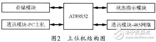
The upper computer is mainly composed of AT89S52 single-chip microcomputer, communication module, storage module and status indication module. Figure 2 shows the structure of its upper computer.
The lower position machine is mainly composed of PIC16 single chip microcomputer, temperature sensor, humidity sensor, fan control unit, status indication module and communication module, and its structure is shown in Fig. 3.
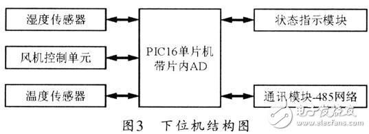
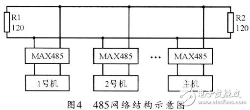
Figure 4 shows a schematic diagram of the networking mode of the 485 communication network based on the Modbus protocol.
4 system software design
The temperature and humidity monitoring system software in this system can be developed by VB language and managed based on Access database. The features of this software are similar to the graphical interface and operation method of Windows, so it is very simple and easy to operate. The main functions completed are data collection, system setup, user management, data processing, data display, system setup, historical data analysis, alarm settings, device management, output reports, and graphical displays. Figure 5 shows the software structure block diagram of the system.
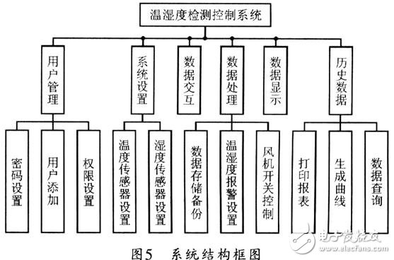
In Figure 5, user management is mainly to manage users of operating software, including user deletion, password management, user rights management, etc.; system settings are settings for monitoring system software temperature and humidity parameters, such as temperature and humidity. The setting of the address parameter of the sensor; the data interaction mainly completes the software to read the data stored in the upper computer; the data processing is mainly responsible for the data storage backup, the setting of the temperature and humidity alarm value, the processing of the read data, and whether the switch is needed. Fan; data display main
It is to display the temperature and humidity of the collection according to the specific needs; the main function of the historical data is to view, analyze and count the previous temperature and humidity records, which can be used by the software for the average temperature or one day of each year, every month, every day. The temperature and humidity at a certain time are queried, including observations of historical data temperature and humidity curves, and printing of temperature/humidity reports for various time periods.
5 Conclusion
This paper mainly discusses the specific method of collecting and controlling temperature and humidity through 485 network based on Modbus protocol. According to the specific operation in the project, the article gives the specific implementation methods of the system hardware, embedded software, PC software and other aspects, so that the designer can be used as a reference in the development and application.
Single Burner with Built in Hob
Single Burner Gas Stove,Stainless Steel Surface Hob,Single Burner Gas Cooktop,Single Burner Gas Hob
xunda science&technology group co.ltd , https://www.gasstove.be