The development of smart phones in recent years has greatly increased the demand for RF front-end equipment, and it is very difficult to be compatible with all of these devices. The MIPI Alliance currently has a set of RFFE standards that connect all RF front-end equipment with the same bus interface. So how is the MIPI-RFFE protocol debugged and tested?
I. Introduction to MIPI-RFFERFFE is the control specification proposed by the MIPI Alliance for RF front-end equipment. One host can be mounted on a single bus, and up to 15 slaves can be mounted at the same time. The bus uses two signal lines, one is the host-controlled clock line SCLK, the other is the bidirectional data line SDATA, in addition to a reference voltage line VIO. The VIO can be provided by the host or externally. The standard frequency of SCLK is 32kHz-26MHz, the expansion frequency is 26MHz-52MHz, and SCLK and SDATA remain low when idle.
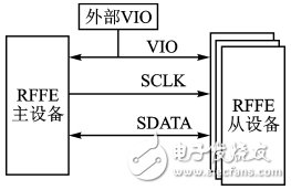
Figure 1 RFFE system
RFFE defines a wide variety of command sequences for reading/writing devices on the bus. Each command contains: start sequence (SSC), command frame (Command Frame) and data sequence Data Frame, as shown in Figure 2 is the timing of register write instructions.
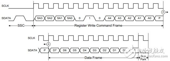
Figure 2 Register Write Instructions
Second, the use and testing of the RFFE protocolBefore the unified interface, it was quite difficult for device manufacturers to design control schemes for all chips. MIPI introduced a unified RFFE control bus to simplify the interface. The advantage of the unified interface standard is that manufacturers can flexibly select different chips and modules from the market according to their needs, which is faster and more convenient when designing and changing functions. With the increasing use of RFFE, there is an increasing demand for RFFE testing in the industry. There are two main requirements for RFFE testing, one is RFFE decoding and triggering, and the other is RFFE timing analysis. All along, manufacturers have to manually analyze the decoding process and timing after capturing the data. This hard work will be liberated by the ZDS4000 oscilloscope. The ZDS4000 Series oscilloscopes fully support MIPI-RFFE analysis, including decoding, triggering and timing analysis, and automated analysis and testing will bring you a whole new experience.
Third, the RFFE analysis method on the ZDS4000Figure 3 shows the communication routine of RFFE. It is very simple to analyze the bus using ZDS4054. Connect the oscilloscope probe to the SCLK and SDATA lines respectively, collect the bus communication data, and then start the MIPI-RFFE protocol decoding. After setting the parameters, you can Complete the protocol analysis.
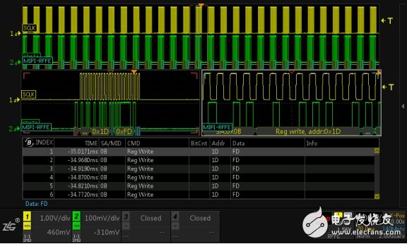
Figure 3 RFFE protocol analysis
You can also capture the data you want with powerful triggering capabilities. The ZDS4000 supports RFFE commands and data triggering. Simply set up as shown in Figure 4 to quickly trigger target data and accurately locate the communication process.
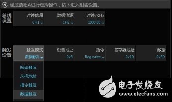
Figure 4 RFFE trigger settings
The ZDS4000 also has powerful timing analysis capabilities, enabling MIPI-RFFE timing analysis in Analyze, and relying on our complete test program to quickly identify possible problems and risks in timing. As shown in Figure 5, the data valid time test does not pass. Just select the item and then press the B knob to immediately locate the position where the test does not pass.
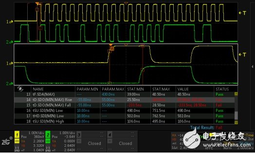
Figure 5 RFFE timing analysis example
UV Roll Material Film,screen protector film roll,screen protector material roll
Guangdong Magic Electronic Limited , https://www.magicmax.cc