The working principle and usage of the 51 MCU timer are essential for embedded system development. The TMOD register is used to configure the operation mode of the timers. It is an 8-bit register, with the upper four bits controlling Timer 1 (T1) and the lower four bits controlling Timer 0 (T0). There are four different operating modes available for each timer, which can be set by configuring TMOD accordingly. For example, setting TMOD to 0x00 selects Mode 0, while 0x01 is also Mode 0, 0x02 is Mode 2, and 0x03 is Mode 3. Since the lower four bits are for T0, these values directly affect how Timer 0 operates.
TR0 is the enable bit for Timer 0. When TR0 is set to 1, the timer starts counting; when it is 0, the timer stops. Similarly, ET0 controls whether Timer 0 can trigger an interrupt. If ET0 is 1, the timer will generate an interrupt once it overflows; if it's 0, interrupts are disabled. EA is the global interrupt enable bit. Think of it as the main switch for all interrupts. When EA is 1, interrupts are allowed; when it's 0, all interrupts are blocked.
TH0 and TL0 are the high and low bytes of the 16-bit timer counter for Timer 0. Together, they form a value ranging from 0x0000 to 0xFFFF (0 to 65535). When TH0 and TL0 reach 0xFFFF, an overflow occurs, and the timer triggers an interrupt. In the interrupt service routine, you need to reload TH0 and TL0 with the initial value to start the timing again.
For example, if you want to time 50 milliseconds, you need to calculate the initial value that should be loaded into TH0 and TL0. Since 50ms equals 50,000 microseconds, the timer must count up 50,000 times before triggering an interrupt. To achieve this, you would set TH0 and TL0 to (65535 - 50000), which is 15535. Then, in the interrupt service routine, you reset them to the same value so that the timer can repeat the process every 50ms.
To compute the exact values for TH0 and TL0, you can use the following formulas: TH0 = (65535 - 50000) / 256 and TL0 = (65535 - 50000) % 256. This ensures that the timer counts correctly and triggers at the desired interval.
Here’s a simple example of a program that sets up Timer 0 to generate a 20ms delay:
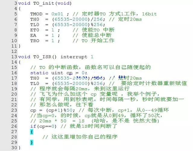
This is a basic example of a 20ms Timer 0 program. Once Timer 0 is configured, what about Timer 1? As I mentioned earlier, Timer 0 and Timer 1 are similar but operate independently. If you take the above Timer 0 example, you can adapt it for Timer 1 by changing the relevant registers and interrupt vectors.
For Timer 1, you would set TMOD to 0x10, enable the interrupt with ET1, start the timer using TR1, and load TH1 and TL1 with the appropriate values. The interrupt vector for Timer 1 is usually Interrupt 3. So, the configuration for Timer 1 becomes: TMOD = 0x10, ET1 = 1, TR1 = 1, TH1 and TL1 initialized with the calculated value, and the interrupt service routine located at address 0x001B.
Rubber Gasket, Industrial Rubber Gasket, Rubber Seal Ring
Wenzhou Hesheng Electronic Co., Ltd. , https://www.heshengelec.com