Pulse Width Modulation (Pulse Width Modulation) refers to fixing the basic period of the output signal and controlling the output power by adjusting the working period of the basic period. The principle is that the on-time of the switch tube in one cycle is t, and the period is T, then the average voltage across the motor is U=Vcct/T=αVcc. Where α = t / T (duty cycle), Vcc is the supply voltage.
PWM often replaces digital-to-analog converters (DACs) for power output control, where speed control of DC motors and AC motors is the most common application. Usually, the PWM is matched with the bridge drive circuit to realize the DC motor speed regulation, which is very simple and has a large speed regulation range.
2, Intel8253 internal structure and working mode 2.1, Intel8253 internal structureThe Intel8253 is a microcomputer peripheral interface circuit that contains three independent 16-bit subtraction counters. Each counter can be determined by software as a 16-bit binary subtraction counter or a decimal 4-bit BCD subtraction counter. Each counter has 6 different operating modes and is also determined by the software. Each counter has a clock input (CLK), a gated signal input (GATE), and an output (OUT). Read and write is controlled by pins such as A1, A0, RD, WR and CS. It is mainly used to control the writing, reading and prohibition of data and commands of Intel8253. The pin arrangement of Intel8253 is shown as U3 in Figure 1.
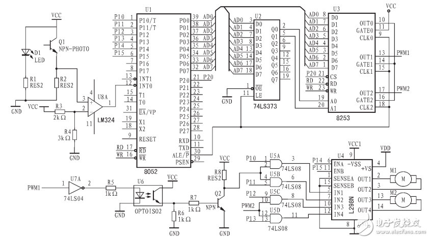
Figure 1 uses Intel8253 and L298N PWM speed control circuit
2.2, working mode related to PWMThe modes of operation associated with PWM are Mode 1 and Mode 2.
(1) Mode 1
When a counter is set to mode 1, the microcomputer can send 16-bit data M to the counter through two output commands. At this point, there is no response at the output of the counter. Once the rising edge of the counter's gate input pulse arrives, its output immediately outputs a negative pulse of width MÏ„, as shown in Figure 2.
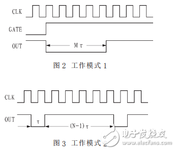
(2) Mode 2
When a counter is set to mode 2, the microcomputer can send 16-bit data N to the counter through two output commands. After the output command ends, the counter immediately outputs a continuous square wave of period NÏ„, as shown in Figure 3.
If the counter 0 and counter 1 of the 8253 are set to mode 2 and mode 1, respectively, and connected as shown in Fig. 4, a very simple pulse width modulation generator can be obtained. Before the start of the work, the constant N is sent to the counter 0, and the constant M is sent to the counter 1 (M "N), so the counter 0 will output a continuous square wave of period NÏ„. The gate input of counter 1 receives a positive transition signal every NÏ„ time. Therefore, every NÏ„ time counter 1 will output a negative going pulse of width MÏ„. Therefore, by changing M and N, a PWM wave with adjustable duty cycle can be obtained.
Reactive Power Compensation Device
Reactive Power Compensation Device,High Voltage Reactive Power Compensation Device,Frame Type Reactive Power Compensation,Outdoor Frame Type Reactive Power Compensation Device
TRANCHART Electrical and Machinery Co.,LTD , https://www.tranchart-electrical.com