In the push-pull, bridge, and half-bridge switching power supply circuits of the low-voltage output, the secondary of the transformer is mostly a conventional double-half bridge rectifier circuit. However, the structure of the transformer in the circuit is complicated, and the capacity of the transformer is required to be relatively large. The improved double-half-wave rectifier circuit described in this paper can simplify the circuit structure of push-pull, bridge, and half-bridge and improve the utilization of isolation transformer. The following is a comparative analysis of the working principle of the two rectifier circuits.
2 traditional double half wave rectifier circuitIn the traditional double half-wave rectification circuit, the center tap of the transformer secondary coil is connected to the output negative terminal. The center tap divides the secondary coil into two sources of opposite polarity and leakage inductance. However, their magnetic structure cannot reach the ideal state, and the initial deviation caused by the two leakage sensations, which cannot be completely equal, has a great influence on the normal operation of the circuit. In addition, the primary winding of the isolation transformer is short-circuited by freewheeling, during which freewheeling also has an effect on the current distribution in the secondary winding. All of these are issues that should be noted in traditional double-wave rectification.
The working principle of this circuit and its working process are as follows:
According to FIG. 1, during the active period of the positive half cycle of each duty cycle, VD1 is in an on state and VD2 is in a blocking state. The current ILO through the inductor LO flows through N21, and there is no current on N22. During the freewheeling period, the voltage across N21 and N22 is zero. In theory, the output current should be evenly distributed between the secondary coils N21, N22. However, in reality, since the leakage inductance is related to the actual magnetic circuit structure, the output current cannot be evenly distributed between N21 and N22.
N21 releases most of the energy, I21 decreases, and N22 increases the current through the leakage inductance and its effective voltage, thus completing the freewheeling process. During the effective period of the negative half cycle, VD1 is blocked, VD2 is turned on, and N22 and VD2 bear all currents on the LO. During the next freewheeling period, the voltages across N21 and N22 become 0 again, and N22 releases the current as in the freewheeling period described above (the main waveform is shown in Figure 2).
It can be seen from the above analysis that N21 and N22 not only supply the load current during the freewheeling period, but also provide the load current when the connected diodes are turned on. In this way, not only the current effective value of the coil is increased, but also the capacity of the transformer is increased, and the magnetic circuit structure of the two coils also causes a large difference between the current value and the theoretical value.
3 improved double half-wave rectifier circuitIn order to complete the conversion from the traditional double-wave rectification to the improved double-half-wave rectification, the working principle of the single-ended forward converter can be utilized to decompose the working process of the transformer into two parts, namely the positive half-cycle working process and the negative half-cycle working. process. This results in the circuit shown in Figure 3, an improved dual half-wave rectification circuit. It consists of a transformerless secondary winding with no taps, two identical rectifier diodes, two identical identical filter inductors and the same filter capacitor as a conventional double half-wave rectifier circuit.
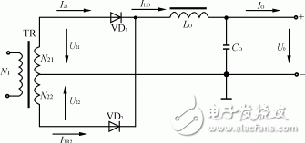
Figure 1 Traditional double half-wave rectifier circuit
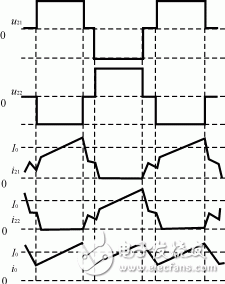
Figure 2 Traditional double half wave rectifier circuit waveform
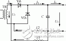
Figure 3 improved double half-wave rectifier circuit
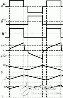
Figure 4 Improved double half-wave rectifier circuit waveform
The working process of the circuit is: during the positive half cycle of each working cycle, the voltage U2 across the secondary winding of the transformer is positive, VD1 is positively biased, VD2 is reverse biased, and VD1 is in the rectification and freewheeling state at the same time. . L1 is continuously discharged through the VD1 and the path. The current of L2 flows through the secondary winding of the transformer, forming a closed loop with VD1, C. The output current is the sum of the DC components of the two filter inductor currents IL1, IL2. The transformer only flows half of the load current during the positive half-cycle effective period. The voltage UL1 across L1 is negative, IL1 gradually decreases, UL2 is positive, and IL2 increases. After the positive half-cycle period, a freewheeling interval is followed, the U2 voltage is zero, and I2 drops rapidly to zero. VD2 turns on to form the freewheeling path of L2, IL1 continues to decrease, UL2 becomes negative, and IL2 decreases. When the negative half cycle effective period comes, the transformer secondary coil voltage U2 becomes negative, VD2 is in positive bias conduction, and VD1 is reverse biased. Similarly, VD2 also has the function of rectification and freewheeling. The current I2 on the secondary coil of the transformer changes direction rapidly, and its magnitude is equal to the current value IL1 on L1. During the VD2 rectification process, the secondary winding of the transformer, VD2, C and L1 form a loop. The voltage UL1 across L1 becomes positive, L1 stores energy, and current IL1 begins to increase. L2 releases the energy storage through the VD2 free-wheeling current, and the IL2 current decreases. When U2 is again 0, another freewheeling starts. The voltage UL1 across L1 becomes negative, so that IL1 decreases and the current of L2 keeps decreasing. Then repeat the above process (main waveform as shown in Figure 4).
4 comparative analysisIt can be seen from the comparison and comparison of the working principle of the traditional double-half-wave rectification and the improved double-half-wave rectification circuit that the latter does not require a center tap, which saves the number of turns and the imbalance of the magnetic structure due to the center tap. Thereby, the DC magnetization problem caused by the fact that the DC component in the secondary coil cannot be cancelled due to the asymmetry of the magnetic structure is eliminated. And the capacity of the transformer is reduced, the structure of the circuit is simplified, power consumption is reduced, and the size of the transformer is reduced. The stress of the diode and filter capacitor in the improved double-half-wave rectifier circuit is the same as that of the conventional double-half-wave rectification, except that a filter inductor is added, and the current on each filter inductor is only half of the output current. The ripple currents on the two filter inductors cancel or partially cancel each other, which can reduce the capacity of the filter capacitor or reduce the inductance of the filter inductor, and the transformer secondary coil takes about half of the output current, and the secondary coil current capacity If it is reduced to the former, if the freewheeling is considered, it can continue to decrease by about 7%. Therefore, the improved dual half-wave rectification technique provides a simpler circuit structure for use with push-pull, bridge, and half-bridge circuits.
The New Electric Power energy stabilizer is a device to stabilize the input voltage, which is composed of a voltage regulating circuit, a control circuit, and a servo motor. When the voltage fluctuation is caused by the voltage fluctuation or load change of the external power supply network, the control circuit will sample, compare, and amplify, and then drive the servo motor to rotate, so that the position of the voltage regulator changes. By automatically adjusting the coil turn ratio, the output voltage can be automatically maintained stable. It has the advantages of large capacity, high efficiency, no waveform distortion, stable voltage regulation, etc. It is applicable to a wide range of loads, can withstand instantaneous overload, can work continuously for a long time, manual/automatic switching, is equipped with overvoltage protection, phase loss, phase sequence protection and mechanical fault automatic protection, and has the advantages of small size, light weight, convenient use and installation, reliable operation, etc
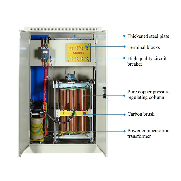
Three-phase voltage stabilizer,Voltage regulator,Automatic Voltage Regulator,380V Ac Voltage Stabilizer
Henan New Electric Power Co.,Ltd. , https://www.newelectricpower.com