High Power Microwave (HPM) or high-energy microwaves generally refer to electromagnetic waves with a peak power of more than 100 mW and an operating frequency of 1 to 30 GHz (corresponding wavelength of 300 to 10 mm). Studies have shown that when the microwave power density reaches O. When 01~1μW, /cm2, the radar and communication equipment working in the corresponding frequency band can be interfered and cannot work normally; when the power density reaches O. When 01~1 W/cm2, the performance of microwave devices in radar, communication, navigation and other equipment can be reduced or invalid; when the power density reaches 10~100 W/cm2, the electronic components working in any band can be invalidated, resulting in The loss of function of the weapon equipment, resulting in the consequences of machine damage. Therefore, research on high-power near-field Cassegrain antenna systems is necessary.
In high-power microwave weapon systems, the main function of the antenna is to concentrate the radiated high-power microwave electromagnetic energy into a very narrow beam, so that the microwave energy is highly concentrated, so that the target is fired at a very high energy intensity, destroying the weapon system and Damage to warfighters. At present, double-reflection antennas are usually selected at home and abroad as the basic form of the system. The main difference between a high power microwave antenna and a conventional antenna is its power capacity. In order to avoid sparking, the ring focus antenna and the Gregory antenna will be excluded because the inherent structure will cause severe air breakdown due to secondary focusing, so the near-field Cassegrain antenna form is selected.
In actual engineering design, due to the size of the working platform, in order to obtain good performance indicators, it is necessary to balance two contradictions:
(1) The contradiction between the high power and the high index, that is, the high power requirement feed source has a large size, which means that the size of the secondary surface cannot be too small, otherwise there will be a leak, which will reduce the effective area of ​​the main surface;
(2) The contradiction between the limited space and the high index, the main surface size and the sub-surface size of the antenna cannot simultaneously satisfy the requirement that the sub-surface diffraction loss is sufficiently small and the sub-surface level is sufficiently low, and thus the main lobe gain is lost.
This paper systematically gives the design of a high-power near-field Cassegrain antenna. The exponential multimode horn with smooth inner wall meets the requirements of high power microwave antenna for high power capacity and good radiation characteristics of the feed. The smooth inner exponential multimode horn-loaded dielectric lens can realize the plane wave illumination of the near-field Cassegrain antenna. Finally, on the basis of balancing the two contradictions, the X-band high-power near-field Cassegrain antenna structure size is obtained through optimization design, and its theoretical power capacity is greater than 600 mW. The measured results agree well with the simulation results, which proves the feasibility of the design.
1 Analysis of the near field card antenna modelAs shown in Fig. 1, the near-field Cassegrain antenna is a special case of the Cassegrain antenna. It uses a paraboloid as a secondary surface and illuminates the secondary surface with a plane wave, and the main surface and the secondary surface of the antenna are confocal. O point. The multimode horn loads the dielectric lens as a feed that is capable of radiating a plane wave. This feed has the following advantages:
(1) axial radiation, good directivity;
(2) Simple structure and high power capacity;
(3) Using plane wave illumination, the leakage of the secondary surface is small;
(4) It is easy to seal, and the dielectric lens on the horn can be used as a sealing cover at the same time.

1.1 Index type multimode speaker
The physical mechanism of the multimode horn can be expressed as follows: Usually, since the main mode is a TE11 mode horn, the E plane pattern is narrower than the H plane pattern, and the rotation axis symmetry radiation pattern cannot be formed, and the peak cross polarization level is also It must be high. The TE1n mode contributes to the H- and E-plane patterns, while the TM1n mode contributes to the E-plane pattern and does not contribute to the H-plane pattern. If a device for generating high-order mode TM11 and other higher-order modes is introduced into the main mode feed, and the relative phase of the higher-order mode and the main mode is properly configured, the TM1n mode is fully utilized to contribute only to the E-plane pattern, and The H-plane pattern does not contribute to this characteristic, and a rotationally symmetrical pattern can be obtained to achieve the purpose of equalizing the beam.
The basic mechanism of the smooth inner exponential curve horn operation is that as the curvature of the horn curve changes continuously, the higher order mode is continuously excited, so that the beam can be shaped by the curve, and finally the horn radiation pattern has a rotation axis. symmetry.
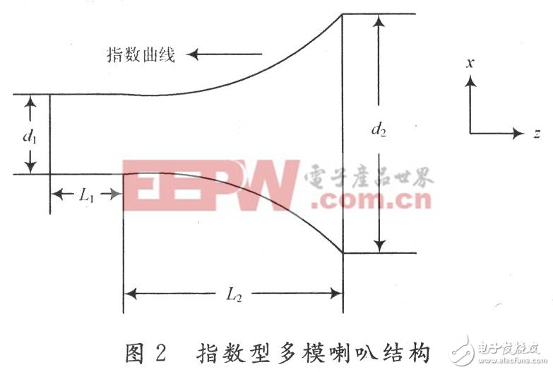
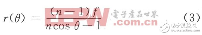
The structure of the exponential multimode horn is shown in Figure 2. The main parameters are: the diameter d1 of the input circular waveguide, the diameter of the exponential bell face d2, the length L1 of the input end circular waveguide and the length L2 of the horn exponential line portion. Among them, the exponential curve satisfies the following exponential equation:
![]()
The principle of the exponential multimode loudspeaker design is to change the parameters of the exponential equation to shape the beam, and finally the direction of the horn radiation has rotational axis symmetry. If a = 1 and c = 0, then the adjustable parameters of the exponential equation leave k and q. The electromagnetic simulation software can be used to simulate and optimize the exponential multi-mode horn, and determine the k and q in the exponential equation to obtain the exponential multi-mode horn that meets the requirements.
1.2 Hyperbolic media lens
The dielectric lens horn antenna is a conventional microwave antenna and has been widely used. Consider the engineering achievability and power capacity issues. Design a compact high power feed, the preferred dielectric lens. The refractive index of the dielectric lens is greater than 1, which is designed according to two basic principles of geometric optics:
Fermat principle: light or electromagnetic waves travel along the path of the optical path;
Snell's law: The law of refractive index when light or electromagnetic waves pass through the boundary faces of two different media is:
![]()
Where: θi is the angle of incidence; θt is the angle of refraction; n is the index of refraction of the second medium relative to the first medium.
Figure 3 is a schematic view of a hyperbolic media lens, which is a single-sided lens, that is, only one surface refracts the microwave ray, the first surface (illumination surface) is a rotating hyperboloid, and the second surface is a plane . Among them, the paraboloid of rotation is:
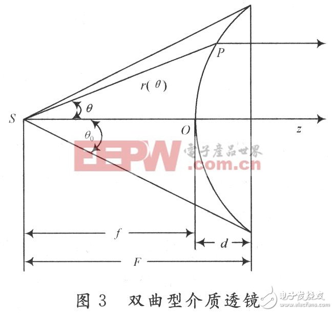
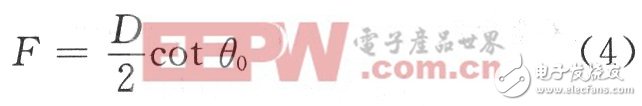
For the dielectric lens to be loaded on the horn diameter, if the half angle of the horn is θ0 and the horn diameter is D, the geometric relationship can be used to determine the distance from the focus of the horn lens to the second surface (plane) of the lens:
The distance from the vertex of the lens hyperboloid to the focus (ie, the focal length f) and the lens thickness d can be further obtained by the equations (3) and (4).
For the design principle of the lens: first find the phase center of the horn, determine the value of F; then determine the value of θ0 according to the value of D; finally select the material of the lens as needed, and determine the f value.
1.3 Analysis of power capacity
The maximum electric field Emax of the outer surface of the dielectric lens at a corresponding input power of 1 W can be obtained by calculation. Since the power is proportional to the square of the magnitude of the electric field, when the maximum power input to the feed is Pimax, the electric field of the outer surface of the dielectric lens can be obtained as:
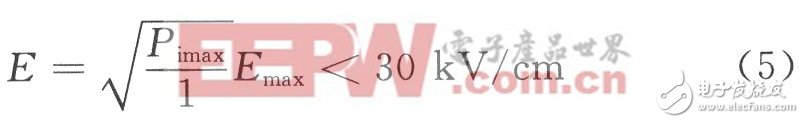
It is generally considered that the continuous wave electric field breakdown threshold in air is 30 kV/cm. Therefore, in the case where the feed output power satisfies the equation (5), air breakdown does not occur in the aperture. In fact, the current high-power microwaves are mostly short-pulse microwaves of several tens of nanoseconds. In the case of short pulses, the breakdown threshold of the atmosphere is greater than 30 kV/cm, so the feed is considered from the air breakdown angle of the surface of the dielectric lens. The source's power capacity is greater than Pimax.
1.4 Main and auxiliary faces of the near field card antenna
Figure 4 is a schematic diagram of the structure of the near-field Cassegrain antenna.
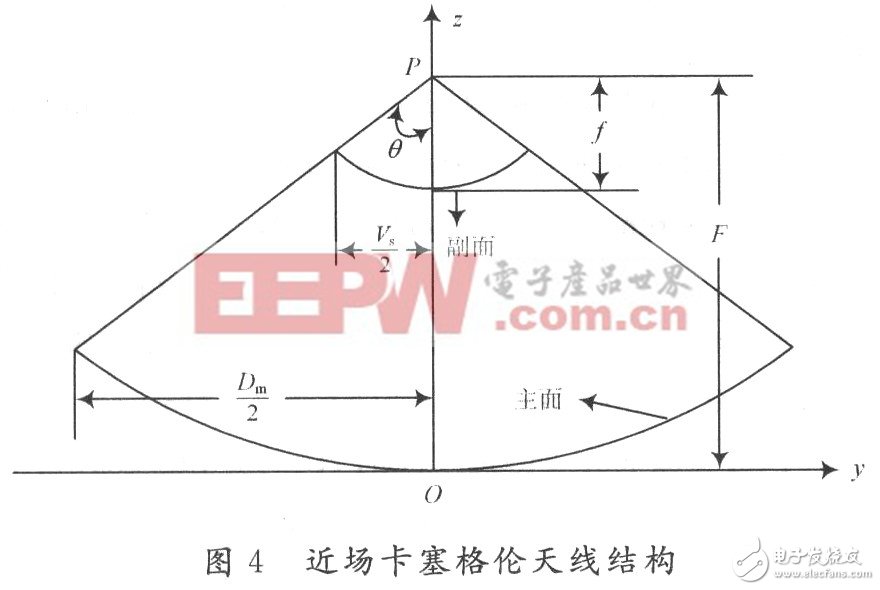

(4) The half angles of the main and auxiliary faces are:
![]()
According to the requirements of the index, an electromagnetic field simulation software was used to optimize the design and processing of an X-band near-field Cassegrain antenna, and the electrical performance was measured. The simulation results and measurement results of the feed were compared. Wherein, the dimensions of the various parts of the antenna system are as follows:
Dimensional multimode horn size: d1=0.05 m, d2=0.266 m, L1=0.013 m, L2=0.507 m; exponential equation parameters: a=1, c=0, k=0 .333, g=3.
Hyperbolic media lens size: F = 0.5 m, f = 0.465 m, n = 1.5, θ0 = 14.9 °, the material of the dielectric lens is polyethylene.
The size of the main and auxiliary faces of the near-field card antenna: Dm=2.2 m, Vs=0.332 m, F=0.836 m, f=0.126 m, θ=66.58°.
Figure 5 shows the near-field Cassegrain antenna. The antenna is measured in a microwave darkroom. It can be seen from Fig. 6 that the maximum electric field of the outer surface of the dielectric lens is less than 110 V/m, and when the input power is 600 mW, the equation (5) is satisfied, so the power capacity of the feed is greater than 600 mW.

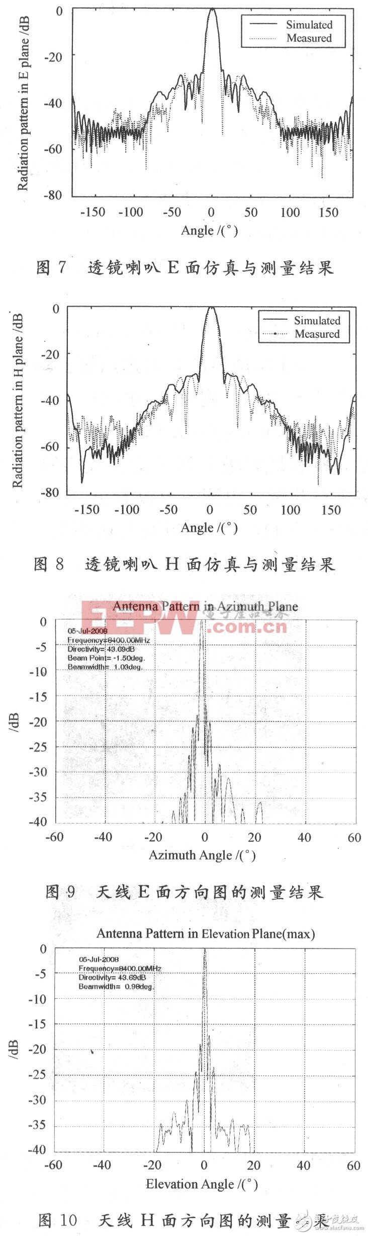
7 and 8 show simulation results and measurement results of the E-plane and the H-plane of the exponential multimode loudspeaker loaded with the dielectric lens, respectively. It can be seen from the comparison that the measured results agree well with the simulation results, indicating that the feed design meets the requirements.
Figure 9 and Figure 10 show the measured results of the design of the near-field Cassegrain antenna horizontal plane (E-plane) pattern and the elevation plane (H-plane) pattern, respectively. The measurement results show that the designed antenna electrical performance fully meets the requirements of the index. This also means that the exponential horn is a highly efficient feed with high power capacity and axisymmetric pattern suitable for use as a feed for high power near-field Cassegrain antennas.
The design scheme of the high power near-field Cassegrain antenna is systematically given. In view of the high power microwave antenna requirements for high power capacity and good radiation characteristics of the feed, an exponential multimode horn with a smooth inner wall is selected. The dielectric lens is loaded on the multi-mode flare surface to meet the plane wave illumination of the antenna sub-surface. By optimizing the design, an X-band high-power near-field Cassegrain antenna with a power capacity greater than 600 mW was obtained, and the measured results were in good agreement with the simulation results. This proves the feasibility of the design.
lightning cable apple,apple lightning to usb cable,USB to type c,micro usb cable,type c to usb cable,usb-a,type c cable,iphone usb-c,type c to usb 3.0 adaper
Mietubl Global Supply Chain (Guangzhou) Co., Ltd. , https://www.mietublmachine.com