Abstract: Rechargeable batteries are the core components of electric vehicles, which directly affect the performance of electric vehicles, and an effective charging method can improve the life of power batteries. The charging main circuit and control circuit are designed. The simulation circuit model is built for the lead-acid battery in the PSCAD environment. The self-recovering positive and negative pulse charging and discharging strategy is used to verify the effectiveness of the charging and discharging strategy. For other kinds of batteries. It also has reference significance.
Keywords: battery; charging strategy; electric car
1 Introduction Power battery is the main source of energy for electric vehicles. Its performance will directly affect the mileage of electric vehicles. The battery life is closely related to the charging and discharging method. During the charging process of the battery, the charge buildup generates a reverse voltage on the battery electrode, which is manifested by an increase in the internal resistance of the battery. At the same time, as the battery is used, the sulfide attached to the internal electrode of the battery also increases, resulting in an increase in the internal resistance of the battery. Big, both of these factors affect the speed and quality of charging. An effective way to eliminate them is to use a negative pulse, which is instantaneously discharged at both ends of the battery to remove the accumulated charge on the electrode, thereby changing the charging characteristic in the form of an exponential curve of the battery, and adopting this new charging in the constant current and constant voltage charging process. The strategy can improve the battery charging acceptance and improve the efficiency and endurance of the electric vehicle.
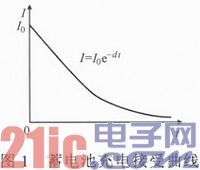
2 Determination of the maximum charging current shows that if the same amount, a small amount of gas precipitation and a stable temperature rise are maintained during the charging process, the charging curve is an exponential curve. The maximum charging current curve of the battery is shown in Figure 1. This is a natural acceptance curve. If the charging current is on the right side of the curve, that is, the charging current is greater than the acceptable current, it will cause electrolyzed water inside the battery; if the charging current is on the left of the curve On the side, the charging current at this time is the acceptable current for charging.
This article refers to the address: http://
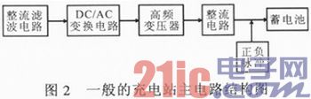
3 Charging station main circuit design The charger function module includes an input rectification circuit and a power conversion circuit. The main circuit structure diagram of the charging station is shown in Figure 2.
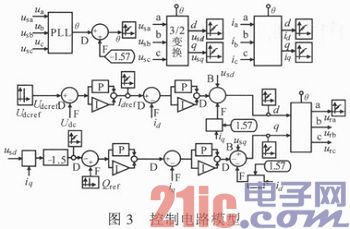
The charger adopts full-control power electronic components as the control core. As shown in Fig. 3, the control circuit adopts double closed-loop control that reaches the power factor sine wave current, and the current inner loop is controlled by the current command output by the voltage outer loop. The voltage outer loop controls the DC side voltage of the three-phase voltage type PWM rectifier.
The circuit can realize charging and discharging of positive and negative pulse intermittent operation mode, and can also realize constant current charging and discharging. When the pulse is charged and discharged, the amplitude, time and intermittent time of the charging pulse can be set. During pulse charging, the polarization of the battery generated by positive pulse charging is eliminated by the discharge negative pulse in time, which can reduce the polarization resistance of the battery and improve the charge and discharge efficiency of the battery. The schematic diagram of the main circuit of the pulse charger is shown in Figure 4.
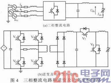
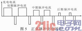
The three-phase 380 V AC power supply is DC-powered by phase-controlled rectifier bridge rectification and LC filtering. When the battery is being charged, the amplitude and time of the charge and discharge pulses are controlled by controlling the intermittent turn-on and turn-off of the two IGBT modules V7, V8. V7 is turned on, and when V8 is turned off, positive pulse constant current charging is realized; when V7 is turned off, when V8 is turned on, negative pulse constant current discharge is realized. The positive and negative pulse duty ratio is shown in Figure 5.
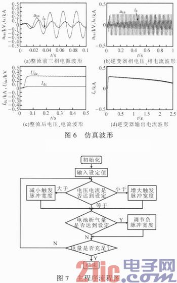
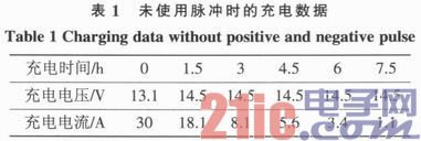
The simulation waveform is shown in Figure 6. It can be seen that the output current of the charger is about 300 A, which meets the requirements for fast charging of the battery. In addition, the main program flow chart shown in Fig. 7 is set in the charging experiment of the battery, and the other parts are general programs, which are not given. The main program is used to complete the battery charging voltage, current and pulse size comparison.
4 Charging parameter selection The charging efficiency was verified by comparing a group of batteries (12 V/60 Ah 5 batteries) with a phased constant current constant voltage charging method and a staged constant current pulse charging method. When the phased constant current pulse charging method is adopted, the charging process of each stage is performed according to the "positive pulse charging → stop charging → negative pulse discharge → stop discharge → positive pulse charging" cycle process. As charging progresses, the charging current decreases step by step.
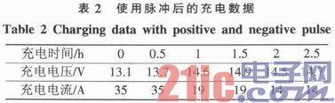
At present, most charging devices on the market adopt a staged constant current and constant voltage charging method. According to the charging requirements of the battery, a constant current charging is performed using a 0.5 C (30 A) charging current at the initial stage of charging. When the charging voltage reaches 14.6 V, it is charged with constant voltage until it is full. Table 1 shows the charging data when no pulse is used.
At the beginning of charging, constant current pulse charging is performed using a charging current of 0.6 C (36 A). The charging current is then reduced in stages to reduce the outgassing rate during charging. Table 2 shows the charging data after the pulse is used.
5 Conclusion The traditional DC charging mode is used to charge the lead-acid battery. The charging efficiency is low. By measuring and comparing the efficiency of traditional DC charging and two kinds of pulse charging, the pulse charging can effectively increase the charging efficiency of the battery and shorten the battery charging efficiency. Charging time and reducing gassing reaction. The pulse current and the charge-discharge time ratio are two major factors affecting the charging efficiency. When the pulse charge-discharge time ratio is 10 and the pulse discharge current is 0.1 mA, the charging efficiency is the highest. It can be seen that this new charging strategy is effective for shortening the charging time, and is also useful for other types of batteries.
Wireless Smartphone Charger,Wireless Charger,Android Wireless Charger,Apple Iphone Wireless Charger
Dongguan baiyou electronic co.,ltd , https://www.dgbaiyou.com