The heart rate acquisition processing circuit is shown in the figure. The part of the circuit is mainly composed of three main circuit modules: pulse pulse infrared detection acquisition circuit module, signal anti-interference circuit module and signal shaping circuit module. Among them, the infrared emission tube D1 and the infrared receiving tube Q1 constitute an infrared detection acquisition circuit; R2 and C1, C2 and C3, R4 and C4 and IC1a together constitute a signal anti-interference circuit group, which respectively bear the low-pass filtering of the signal , the interference of light photoelectric isolation, residual high-frequency interference filtering and other tasks. In addition, IC1b, C5, R10, and IC1c together form a signal shaping circuit module.
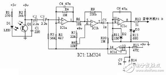
The basic process of heart rate acquisition and processing circuit operation is as follows:
First, in the infrared detection acquisition circuit, D1 emits infrared rays, and Q1 receives the translucency of the corresponding tissue and simultaneously converts it into an electrical signal. Since the pulse is generally between 50 beats/min and 200 beats/min, the corresponding frequency range is between 0.78 Hz and 3.33 Hz, so the frequency of the electrical signal collected and converted by infrared detection is very low. In order to prevent the signal from being wrong due to external high-frequency signal interference, the signal must be low-pass filtered to filter out most of the high-frequency interference. R2 and C1 are used in the circuit to complete the task of filtering out high frequency interference.
Then, since the design of the heart rate monitor is outdoor, it is bound to encounter strong light radiation. In order to avoid the interference of strong light when receiving normal pulse infrared, the circuit is designed to use a bipolar coupling capacitor composed of C2 and C3 back-to-back series to form a simple photoelectric isolation circuit, thus achieving isolation of interference light. In addition, in order to prevent the previous high-frequency interference filtering is not thorough enough, the circuit is also designed to connect a low-pass filter circuit composed of IC1a, R4, C4 with a cutoff frequency of about 10Hz, in order to further filter out the interference, and at the same time The signal is amplified by about 200 times.
The signal obtained by the previous processing is a pulsed sine wave superimposed with noise, and then the signal must be shaped. First, the sine wave is converted into a square wave by the comparator IC1b. The purpose of setting the threshold of the comparator within the amplitude range of the sine wave can be achieved by using R8. Next, the square wave signal output from the 7-pin of IC1b is subjected to differential processing by C5 and R10, and is subjected to differential processing to become a sharp pulse between positive and negative phases. In order to stabilize the pulse output, the circuit is designed to input this pulse to the inverting input of the monostable multivibrator IC1c, and use the output of IC1c as the actual use pulse for the post-pole operation.
When IC1c is working, when there is an input signal, it will output a high level when the trailing edge of the input signal comes, so that C6 is charged through R11. After about 20ms, the potential of IC1c's non-inverting input will decrease due to the decrease of C3 charging current. When this potential is lower than the potential of the inverting input (the sharp pulse has passed for a long time), IC1c will change state and output low level again. . This 20 ms pulse time is synchronized with the pulse, which corresponds to the blinking of the red LED D3 during circuit operation.
After the IC1c pulse is the actual pulse required by the MCU control circuit, after R12 is sent to the P3.3 pin of the MCU, the subsequent counting and display can be realized.
The 4.5V supply voltage required for IC1a, IC1b, and IC1c operation is obtained by dividing R14 and R15 to 9V and buffering it through IC1d. This setting allows the circuit to operate normally even if the battery voltage is reduced to 6V.

About baby bib:
The mothers have common perplex that they worry the baby get dirt on clothes when they have meal.What can we do to avoid that? Many mothers will buy baby bib! However, the baby bib which is made of cloth is easy to get dirty and difficult to clean! Can we solve this problem ? Absolutely yes! Silicone Baby Bibs are not only can help you avoid dirty problems when they have meal, but also easy to clean! Why? Because the silicone material is smooth and waterproof, more important , it can dry quickly which save you a lot of time. So, when mothers choose to buy a baby bib, most of them choose the silicone one!
Product discription:
1.Product name: Baby Bibs Silicone ,Silicone Bibs For Children,Waterproof Silicone Baby Bibs,Food Grade Silicone Baby Bibs, Silicone Baby Feeding Bibs ,Silicone Baby Bibs With Pocket
2.Place of origin:Guangdong China
3.Color:any pantone color
4.Logo:Printing,debossed,embossed
5.MOQ:500pcs.
6.Package:1 pcs/opp,customized design is available.
7.Design:Customized/stock
8.Certification:FDA,LFGB,SGS,ROHS,etc.
9.Usage:Use in baby meal
10.Silicone baby bibs photos for reference.

Silicone Bibs
Baby Bibs Silicone,Silicone Bibs For Children,Waterproof Silicone Baby Bibs,Food Grade Silicone Baby Bibs,Silicone Baby Feeding Bibs,Silicone Baby Bibs With Pocket
Honghao Silicone Gift Co., Ltd. , https://www.oemsiliconegift.com