XML is a machine-oriented data format that, although challenging to write manually, offers high efficiency. Introduced to the software industry in February 1998, XML (Extensible Markup Language) caused a significant shift. It provided the first universally adaptable format for structured documents and data, suitable not only for the web but also for various other applications.
UML modeling visually represents business processes and interactions between software components using diagrams. Common UML diagrams include class diagrams, use case diagrams, state diagrams, activity diagrams, collaboration diagrams, sequence diagrams, and deployment diagrams.
XML Metadata Interchange (XMI), another OMG specification, simplifies data integration by serving as a popular format for representing UML objects. UML diagrams can be stored in XMI format or created from XMI files. This makes it easier to transfer UML chart data, and many UML tools support this functionality.
In this article, we will generate an XMI document using a sample EnterpriseJavaBean (EJB) deployment descriptor called ejb-jar.xml. If you don’t have a tool to automatically store UML diagrams in XMI format, you can use XSLT to generate XMI documents. The XMI file generated from the sample deployment descriptor will display a UML class diagram, which represents the analysis view of the EJB deployment descriptor. This diagram can then be converted into a UML chart in Oracle JDeveloper 10g.
**Preparatory Setup**
To generate XMI documents from XML, the `oracle.xml.parser.v2.oraxsl` class is required. First, download the Oracle XML Developer’s Kit (XDK) and add `XDK10g/lib/xmlparserv2.jar` to your classpath. Make sure to replace "XDK10g" with the actual installation directory. Then, download and install JDeveloper 10g.
**Generating UML Class Diagrams**
As mentioned earlier, UML class diagrams illustrate different entities within a class. In this section, we will create an XMI file for a UML class diagram using the sample EJB deployment descriptor.
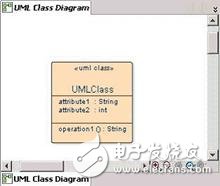
An example of a container-managed persistence (CMP) entity EJB's `ejb-jar.xml` deployment descriptor defines fields and query methods in an EJB class. The UML class diagram created from `ejb-jar.xml` will show the properties and methods of the EJB Bean class and interface. The diagram includes three sections: the top for the class name, the middle for attributes corresponding to EJB fields, and the bottom for methods. An example of such a class diagram is shown in Figure 1.
The XMI representation in a UML class diagram contains XML elements and attributes that correspond to classes, properties, and operations. Below is a list of some key elements in an XMI document:
- **xmi.version**: Specifies the version of XMI.
- **xmlns:UML**: Defines the namespace for UML elements.
- **XMI.content**: Contains the actual data being transferred.
- **XMI.header**: Represents the XMI documentation.
- **UML.Model**: Represents the UML model with attributes like `xmi.id`, `name`, and `isAbstract`.
- **UML:Namespace.ownedElement**: Includes elements like `UML:Class`, `UML:Attribute`, and `UML:Operation`.
- **UML:Class**: Represents a UML class with attributes like `name` and `visibility`.
- **UML:Attribute**: Represents a class attribute with details like `type` and `name`.
- **UML:Operation**: Represents a method in a class with attributes like `name` and `return type`.
- **UML:Parameter**: Represents parameters of a method.
- **UML:Package**: Represents a package containing UML elements.
- **UML:Stereotype**: Represents a template for a class, though not currently supported in JDeveloper.
**Generating an XMI File**
To convert the sample XML document into an XMI file, create an XSLT stylesheet. In JDeveloper, select File > New, then choose General XML and XSLT Stylesheet. For example, the `ejb-jar.xml` file can be transformed into an XMI document named `UMLAnalysisView.xmi` using an XSLT file called `UMLAnalysisView.xslt`. If any fields are not of type String, the XSLT must be adjusted accordingly. The `oraxsl` utility is used for this transformation.
```
java oracle.xml.parser.v2.oraxsl ejb-jar.xml UMLAnalysisView.xslt UMLAnalysisView.xmi
```
All three files are included in the sample code.
**Displaying UML Class Diagrams in JDeveloper 10g**
To import the XMI document into JDeveloper and generate an analysis view class diagram, start JDeveloper 10g and create a new project. Open the XMI document by selecting File > New, then choose “Diagrams†> “UML Class Diagrams from XMI Import.†Select the XMI file (`UMLAnalysisView.xmi`) you want to use for the diagram.
After importing, add a node called `ClassDiagram` for XMI Import to the `UMLAnalysisView.xmi` document in the Applications-Navigator framework. Right-click on the `Class Diagram XMIImport` node and select “Open†to view the UML class diagram.
The resulting diagram will display the class name at the top, attributes in the middle, and methods at the bottom. Each attribute and method includes its respective data type and return type. Additional features such as `ejbSelect` and business methods may also appear in the diagram.
**Conclusion**
As demonstrated, the XMI format simplifies the exchange of UML metadata, making it easy to reconstruct UML diagrams. If you don’t have a UML tool that supports XMI imports, you can directly generate XMI documents from XML, offering flexibility and efficiency in modeling and data integration.
Connecting Terminals,Micro Connecting Terminal,Aluminum Connecting Terminals,Connecting Copper Terminal
Taixing Longyi Terminals Co.,Ltd. , https://www.txlyterminals.com