When it comes to electrical drawings, one of the most common issues that arise is the line numbering problem. In simple terms, a line number serves as a label placed at the wiring point of a wire. But how are these numbers typically marked and standardized in the drawing? What methods are currently used, and how do they differ? This article mainly discusses the labeling specifications for line numbers through Eplan drawings.
Method 1: Connection Point Identification
This method is widely regarded as the most accurate and professional approach. Before diving into line numbering, let’s compare two different drawing styles. In Europe, using Eplan to create schematic diagrams is unique and precise. Every wiring marked in the drawing corresponds directly to its actual physical connection. For example, in the diagram below, the connection points 13/14 and 11/12/14 of a contactor and relay are clearly labeled. The real-world wiring matches this precisely — such as terminal 14 of K02M1 being connected to terminal 11 of K02A. However, many Japanese and Chinese drawing practices omit these connection points, leaving electricians to choose auxiliary contacts based on their own judgment during installation.
In contrast, Eplan diagrams ensure each terminal is uniquely marked and corresponds directly to the real-world setup. Traditional domestic drawings often lack schematic terminals, with labels only appearing on final wiring diagrams. This separation makes it difficult to reference the original design.
The image below illustrates how connection points are identified in Eplan:
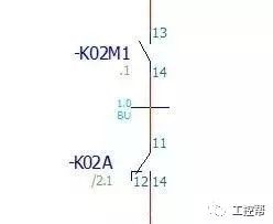
Figure 1 shows that each terminal is uniquely labeled, and the actual wiring aligns perfectly with the drawing. This method reduces the skill level required for electricians, improves consistency, and simplifies troubleshooting. When using accurate drawings, all wiring is based on connection points. These can be considered as line numbers, eliminating the need for additional markings on the schematic.
Some German companies even use the connection points themselves as line numbers, removing device names and prefixes. This approach simplifies the system and avoids unnecessary complexity. While some may argue for including full device names, I believe it's not necessary, especially when using function group names, which can make line numbers too long and cumbersome.
From this, we can see that the main purpose of line numbers on-site is to help identify where wires should be reconnected after replacement or disconnection. However, in accurate drawings, the connection points are already clearly marked, making line numbers less essential. Some German equipment suppliers even skip marking line numbers in the actual cabinet wiring, which might seem odd at first but becomes practical when components need to be replaced or lines disconnected.
Inaccurate drawings often rely on line numbers to establish a relationship between the field and the drawing, though this usually results in non-one-to-one correspondence, making it harder to trace. Accurate drawings, on the other hand, use manufacturer-issued connection points, ensuring perfect alignment between the drawing and the actual wiring.
Summarizing the advantages of Method 1:
1. No need to mark line numbers on the schematic, keeping the drawing clean.
2. Designers don't have to worry about line numbers, improving standardization and speed.
3. Quick restoration of wiring after replacement or disconnection.
4. Simple rules allow electricians to quickly connect wires.
Method 2 involves identifying both ends of a line with connection points, known as "remote echoes." This method requires the full device name plus the connection point, resulting in longer line numbers and increased wiring costs. It’s rarely used in practice due to its complexity.
Method 3 combines automated and manual line numbering. Line numbers are pre-assigned in certain parts of the drawing, while others are manually placed. Eplan allows for both automatic and manual placement, though the latter is still imperfect. This method is more suitable for traditional domestic practices, though it's more complex than Method 1.
Ultimately, whether you use Method 1 or 3, the goal is to ensure the physical wiring matches the drawing. Accurate drawings rely on manufacturer-issued connection points, making line numbers redundant in many cases. For those who prefer line numbers, it's still a useful tool, but it ultimately depends on the drawing quality and the specific project requirements.
In conclusion, accurate drawing methods like Method 1 provide the most reliable and efficient way to manage line numbers, reducing confusion and improving overall project clarity.
Aluminum Laptop Cooling Stand
Aluminum Laptop Cooling Stand,Aluminum Laptop Stand,Aluminum Laptop Stand 17 Inch,Aluminum Laptop Stand Adjustable,etc.
Shenzhen Chengrong Technology Co.ltd is a high-quality enterprise specializing in metal stamping and CNC production for 12 years. The company mainly aims at the R&D, production and sales of Notebook Laptop Stands and Mobile Phone Stands. From the mold design and processing to machining and product surface oxidation, spraying treatment etc ,integration can fully meet the various processing needs of customers. Have a complete and scientific quality management system, strength and product quality are recognized and trusted by the industry, to meet changing economic and social needs .

Aluminum Laptop Cooling Stand,Aluminum Laptop Stand,Aluminum Laptop Stand 17 Inch,Aluminum Laptop Stand Adjustable
Shenzhen ChengRong Technology Co.,Ltd. , https://www.laptopstandsupplier.com