1 Introduction
When the vehicle drive motor is driven by dispersion, it may cause uncoordinated operation of the car body due to the unsynchronized motor speed, which may cause the motor speed to deviate from the normal value. In severe cases, the equipment may be damaged. Therefore, it is of practical significance to solve the problem that the motor speed of the vehicle drive motor is not synchronized when the drive is dispersed.
This paper introduces an advanced and practical control method for solving the motor speed synchronization when the vehicle is dispersedly driven by PLC.
2 Proposal of the problem
At present, the running equipment of the vehicle generally adopts two modes: centralized driving (see Figure 1) and decentralized driving (see Figure 2). The relationship between the drive inverter and the motor is “a lot of dragâ€; the relationship between the two is “one drag and oneâ€.
This article refers to the address: http://
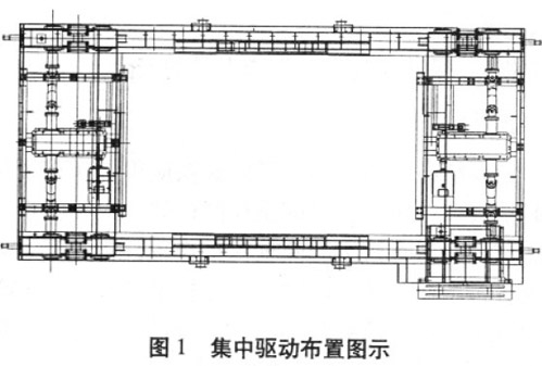
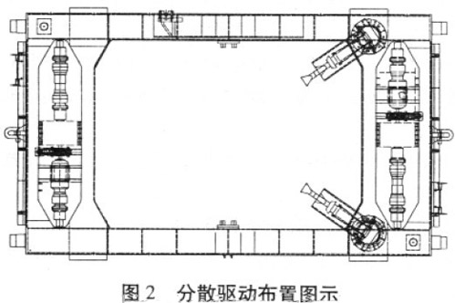
The advantage of “one-to-many†is that the control is simple, the operation and maintenance are convenient, but the centralized drive arrangement requires a large space for the vehicle body. When the vehicle load is large or the space of the vehicle body is limited, the "one-for-one" decentralized driving method is usually adopted because of its compact structure and simple layout. However, a pair of inverters and motors have higher requirements, especially the synchronization problem is difficult to solve. If the motor speeds are inconsistent, the inverter will work in the opposite direction, and the output current will be too large to trip, which will affect the working efficiency of the vehicle and the service life of the electrical equipment. If the deviation of the speed is too large, the vehicle body will be deformed and affect the use.
3 Solutions
The PLC and inverter control methods are used to realize synchronous operation of multiple distributed drive motors. The PLC adopts the Siemens S7400 series, and Figure 3 shows the network topology.
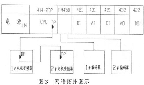
In order to realize the speed synchronization of the two traction motors, two variable frequency motors are used for traction, and the frequency converter is used for vector closed-loop control, and two inverters are directly controlled by PLC. In the control, the Profibus connection between the PLC and the inverter ensures the synchronization of the output signal source. With the speed of the traction motor 1 as the target speed, the speed of the traction motor 1 is adjusted by the frequency converter of the traction motor 2 to track the speed of the traction motor 1. The two incremental rotary encoders are coaxially coupled with the motor, so that encoder 1 and encoder 2 respectively collect the speed pulse signals of the two motors, and send the signals to the high-speed counting module of the PLC. The PLC uses the two speed signal data as the input control amount to perform the proportional integral control operation (PID), and the operation result is sent as an output signal to the analog module of the PLC to control the inverter of the traction motor 2. In this way, the speed tracking of the traction motor 2 can be ensured and varied as the speed of the traction motor 1 changes. Keep the two speeds in sync.
The pulse signal collected from the encoder is input into the PLC through the high-speed counting module FM350-1, and converted into motor speed data. Compare the signals of the two motor encoders, adjust the motor speed difference through the PID adjustment module, and give the motor 2 speed value MW1000.
The MW1000 needs to be converted into a signal that the drive can accept. Since the corresponding 4~20mA value of PLC is 0~27648, the receiving range of the inverter is 0~8192, so MW1000/27648×8192 is sent to the analog output channel and converted into the current signal that the inverter can accept to control the traction motor. The 2 frequency converter, PID algorithm is the most commonly used mathematical algorithm in industrial control, and its basic formula is as follows:
Pou (tt) = Kp × (et) + Ki × Σ (et) + Kd × [ (et) - (et- 1) ]
Where: Kp - proportional adjustment factor. It is proportional to the deviation of the system. Once the system is biased, the proportional adjustment immediately produces a regulation to reduce the error.
Ki - integral adjustment factor. The system eliminates the steady-state error and improves the indifference. The strength of the integral action depends on the integration time. The smaller the constant Ti, the stronger the integral action. Kd—differential adjustment factor. The differential action reflects the rate of change of the system's deviation signal. It is predictable and predicts the trend of the deviation. Therefore, it can produce advanced control effects, which have been eliminated by differential regulation before the deviation has been formed. In order to reduce the external interference caused by factors such as power system fluctuations, in the preparation of the control algorithm, it is necessary to consider the use of the integral link, that is, using a continuous stable input signal for a period of time instead of an instantaneous input signal for PID operation to eliminate accumulation. The error makes the number of revolutions adjustable within a certain range. In this way, the traction motor 1 and the traction motor 2 are well synchronized and have high synchronization accuracy, thus ensuring the stability of the operating mechanism.
4 Control results
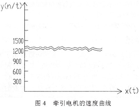
Use STEP7 to program the PLC host computer monitoring program, Wincc collects the speed value and draws the curve. The time interval for data extraction is 15ms. In fact, the speeds of the traction motor 1 and the traction motor 2 are the same, but in order to reflect the tracking and fluctuation of the traction motor 2, it is specifically separated here, above is the speed curve of the traction motor 1, and below is the speed curve of the traction motor 2. (See Figure 4). When the speed of the traction motor 1 changes, the traction motor 2 can respond in time, track, and quickly stabilize. Experiments show that the control method of PLC and frequency converter can achieve higher synchronization requirements, faster response and less fluctuation of speed.
5 Conclusion
This control method has been applied in various downhole vehicles. In practical applications, the synchronous starting effect is obvious, and the vehicle runs smoothly. Practice has proved that the control method of using PLC to solve the motor speed synchronization when the vehicle is dispersed drive is better. It is an ideal speed control method, which satisfies the production process requirements, reduces the maintenance and repair costs of the equipment, and ensures that the vehicle plays normally. The production efficiency and economic benefits are significant. With the wide application of PLC and inverter control methods, the reliability and flexibility of the transmission system for speed control will be better improved.
220Uh Inductor,High Current Inductor,Magnetic Inductor,Toroidal Core Inductor
IHUA INDUSTRIES CO.,LTD. , https://www.ihua-transformer.com