Using fuzzy logic design based on DSP engine controller
More and more companies are using variable speed drive engines to reduce energy consumption. This requires simplifying the design, reducing development time, and eliminating complex mathematical formulas by moving from a differential (PID) controller to a system based on fuzzy logic algorithms.
However, this poses new challenges for the engine. When using traditional integral and derivative (PID) controllers to control the speed of BLDC motors, it is complicated because they rely on complex mathematical models and are computationally intensive. The use of fuzzy logic (FL) algorithms can eliminate the design process's dependence on complex mathematical formulas and provide an easy-to-understand solution. Compared with (PID) differential controllers, fuzzy logic (FL) engine control also has an advantage, that is, the development cycle is shorter. This paper discusses the process of using Texas Instruments c28xx fixed-point DSP series to implement fuzzy logic algorithm to control the brushless DC motor.
The Development of Brushless DC Motor Control Model
Before the construction of the fuzzy logic (FL) engine, we must first establish a model as the basis of the design. The fuzzy logic controller uses heuristic knowledge and uses a language description model to express its design. We will use the PID controller model as a starting point instead of developing a model from scratch. Once developed and implemented, the fuzzy logic controller will improve its performance by adjusting its parameters.
In general, there are three design steps to develop a fuzzy logic brushless DC controller:
1. Define the operating range of the input and output controllers.
2. Define the functions and rules of fuzzy membership.
3. Adjust the engine.
The first step is to define the input and output related to the pattern. The input is the error (E), which is the current error between the set speed (SS) and the current speed (CS); the other input is the change in error (CE), which is the current error and the previously calculated error (PE) The difference between. The output is the changed value of the armature voltage (CV), which is the difference between the existing armature voltage (CAV) and the previous saved value of the armature voltage (PAV). The resulting model equation is as follows:
E = SS-CS
CE = E-PE
CV = CAV-PAV
The unit of engine speed is revolutions per minute (RPM), and E determines how close to the target speed is. Therefore, when E> 0, the rotation speed of the engine is lower than the set speed; when E <0, the rotation speed of the motor exceeds the set speed. CE determines the adjustment direction of the controller. CE is positive if and only if (iff) the current rotation speed is lower than the set speed; if and only if the current rotation speed is greater than the set speed, CE is negative. When approaching the set speed, CE will adjust back and forth between positive and negative values. CV is the supply voltage of the armature. This voltage is expressed as a pulse width modulation (PWM) duty cycle.
The next step is to define the member functions, variables and rules of the fuzzy set. In order to be able to work, non-fuzzy (clear) inputs and outputs must be converted to fuzzy. The conversion consists of using linguistic variables to represent input and output ranges. These are also called fuzzy variables. Fuzzy variables are used to divide the region of membership values ​​for member functions. For example, five variables are used to map input and output. They are medium negative (NM), small negative (NS), zero (z), small positive (PS), and medium positive (PM).
It is not a mathematical formula. The fuzzy controller uses fuzzy rules to make decisions and produce an output. Fuzzy rules are described in the form of IF-THEN sentences. Fuzzy rules determine the behavior of the system, not complex mathematical equations. For example, if the error (E) is equal to a medium negative value (NM) and the change in error (CE) is equal to a small positive value (PS), then the change in armature voltage (CV) is equal to a small negative value (NS). Some rules used are set according to the designer's experience and system knowledge. Therefore, the number of rules used by our system is 25.
In order to activate the armature, the CV fuzzy output must be converted back to a clear output. This process is called deblurring. A popular deblurring method is called the center of gravity method.
The final step in the design is to adjust the member functions and rules. This stage is also called the optimization adjustment stage. The optimization adjustment is used to improve the performance of the fuzzy controller. Once the design is complete, the controller will be ready to be implemented.
The realization of fuzzy logic controller is composed of three modules. They are fuzzification, rule deployment and de-fuzzification. The following sections discuss the implementation of fuzzy logic brushless DC motor related modules.
Blur
Fuzzification is the process of converting data with clear values ​​into fuzzy data. The resulting conversion of fuzzy data is based on the fuzzy membership of the input variables. For this application, the motor control input variables are rotation error (Error) and rotation error difference (Cerror). Rotation error (Error) is the absolute rotation speed difference from one sampling time to the next sampling time. Similarly, the rotation error difference (Cerror) is the change value of the rotation error between one sampling time and the next sampling time. The formula is as follows:
Rotation error (Error) = SetSpeed ​​(set speed)-Cur-rentSpeed ​​(current speed)
Rotation error difference (Cerror) = rotation error (Error) -Pre-viousError (previous error)
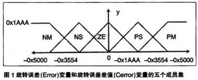
As mentioned earlier, five member sets are defined for the rotation error (Error) variable and the rotation error difference (Cerror) variable:
1. NM: medium negative value
2. NS: small negative value
3. ZE: zero
4. PS: small positive value
5. PM: medium positive value
Figure 1 shows the five member sets defined for the rotation error (Error) variable and rotation error difference (Cerror) variable. These member sets are triangle-shaped overlapping to provide a good response. Each group has a maximum value of 0 × 1AAA.
After the input variable is fuzzified, a vector consisting of five parts is generated, which corresponds to the medium negative value, small negative value, zero, small positive value, and medium positive value of the fuzzified member set. The value of the Y axis corresponding to each component represents the membership of the clear input value. The vector contains the rotation error (Error) and the rotation error difference (Cerror). The fuzzy values ​​are represented as arrays × 1 [] and X2 [].
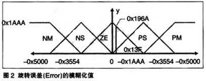
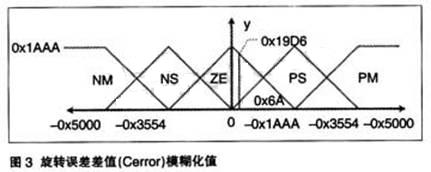
Figures 2 and 3 graphically show the rotation error [Error] and rotation error difference (Cerror) blurring values.
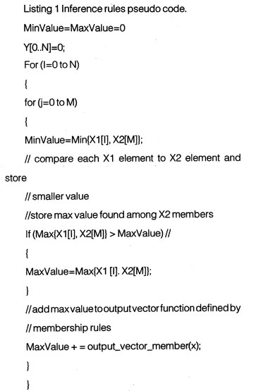
Fuzzy inference rules
Fuzzy inference rules determine system behavior by manipulating fuzzy data. Specifically, the fuzzy data is applied against the rule table. In terms of language, this is the comparison of the input data Error, Cerror and the rule table. The rule table contains the member sets NM, NS, ZE, PS, and PM, and operates according to the control plane. The output is through valid "inferred" or "established" rules. The reasoning process is described in the following pseudo code list:
Deblurring
Deblurring is the process of converting fuzzy data into clear data. For this application purpose, the deblurred value determines the duty cycle of the PWM signal used to drive the motor. The duty cycle depends on using the modified centroid calculation function. The deblurring method used here is to multiply the centroid calculation function by a coefficient. The modified calculation is also called the centroid point calculation function.
The calculation formula of the centroid point is:
Defuzzified VaLue = ∑-Y [i] XmultCoeff [l] ï¼ âˆ‘Y [i]
The i of Y [i] is the output vector element, which is the coefficient by which the output member set of multCoeff [i] should be multiplied. Among them, i can take 1 ~ 5. The formula calculation result is the result after deblurring.
Figure 4 graphically shows the output member set and [-0x10, -0x8, 0x0, 0x8, 0x10] coefficients used by the application.
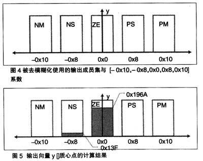
Assuming that y [] = [0x0, 0x13F, 0x196A, 0x0, 0x0], the deblurred output value is as follows:
Defuz = 0 × (-16) + 319 × (-8) + 6506 × (0) + 0 × (8) + 0 × (16) ï¼ 0 + 319 + 6506 + 0 + 0 = -2552 ï¼ 6825 = " -0.37391
Figure 5 shows the calculation results for the centroid point of the output vector y [].
Hardware description
The eZDSP2812 board is used in this motor control application. The core of the eZdsp board is the TMS320F2812 digital signal processor. The board uses timers T1 and 20kHz to generate PWM1-6 signals and uses timer T2 to execute the interrupt service routine (ISR). In addition, the input capture pins CAP1-3 are used to collect high-speed data from Hall effect sensors.
The engine is driven by the PWM signal generated by the DSP. These six PWM signals are used as the source of the three-phase power converter. The power converter converts these six signals into three-phase signals and directly serves as the power supply for the engine. The function of the three-phase power converter is handled by an auxiliary motor control circuit board. Spectrum Digital provides two circuit boards that can provide this function: DMC550 and DMC1500. Any one of them can be directly inserted into the eZdsp28xx board and used.
Hall effect sensors are used for fuzzy logic control loop feedback. The conversion of the three-phase power converter switch is determined by detecting the signal received from the Hall effect sensor. This signal is sent into the collection needle of TMS320F2812. The calculation of the actual motor speed is counted by a software module.
Software introduction
Motor control software is composed of digital microcircuit (DMC) library module and FL motor control program. Seven modules in the Digital Microcircuit (DMC) library are used in this application. They are:
· Datalog data record · BLDC3PWM
· Tall3_Drv
· Mod6_Cnt
· Rmp2Cntl
· Rarnp_Cntl
· Speed_PR
In addition, fuzzy logic engine control is handled by a main FuzzyCtl () routine; for BLDC motors it is Fuzzy-BLDC ().
The software first configures for the first run, and then makes application-specific settings. Specifically, the GPIO pins are configured as CAPture and PWM pins.
The next step is to initialize the timer and module parameters and set the ISR. When all peripherals are set up, the interrupt is activated and enters the main control system. The main control system calls the fuzzy controller every 8.7 milliseconds.
The error value is converted into a fuzzy value through blurring and stored in X1 [] and X2 []. Once converted, the fuzzy value is applied to fuzzy inference rules.
The results obtained from the inference module are stored in Y []. The output from Y [] is converted to a clear value in the defuzzification module. The resulting clarity value is a PWM offset that is added to the current PWM duty cycle. The updated PWM value is checked to see if the new value is within a certain range, and if not, appropriate action will be taken. Finally, the fuzzy controller returns the updated PWM duty cycle to the calling routine.
Figure 6 shows the debugging of the demo application.
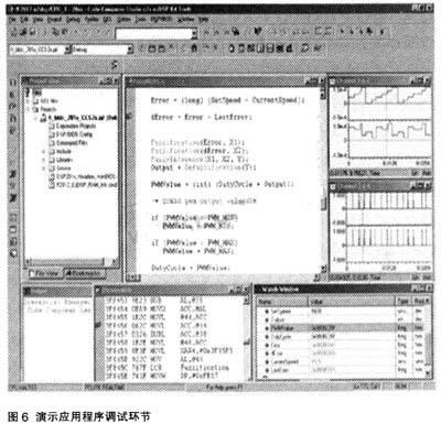
Channels 1 and 2 (the display window in the upper right corner) show the PWM counter and the captured Hall effect sensor, respectively. Channels 3 and 4 (below channels 1 and 2) show the version of the edge-triggered PWM counter and the display window of the Hall effect sensor. The monitoring window displays important variables, the most important of which are SetSpeed ​​and CurrentSpeed. These values ​​are close enough so that the output of the fuzzy logic controller is zero.
This session showed that the engine was running under no-load conditions. This behavior may be slightly different from the situation under load. In addition, if you want finer granularity, it may be necessary to adjust the controller.
Multi-core cpu is more and more popular, people are used to take dual core processors laptop before. However, Quad Core Laptop is becoming selling like a hot cake nowadays. You can find Quad Core Processor Laptop at our store, like I3 Quad Core Laptop,I7 Quad Core Laptop, I5 Quad Core Laptop, intel celeron J4125 or N5095 15.6 Inch Laptop, even N4120 quad core 14 Inch Laptop, etc. Therefore, you can just share the parameters prefer, like size, cpu, ram, rom, gpu, application scenarios, thus save much time to get a win-win solution.
Do you know the reason why more people choose quad core device? The core reason is that heavier tasks people need to finish at a higher speed than before. Nowadays quick rhythm is becoming the main style in city even everyone is eager to downshifting. So more powerful laptop, computer, mobile phone is a trend, though most functions never are used in lifetime.
Other 15.6 inch Gaming Laptop or 14 Inch Gaming Laptop is becoming the most popular level at the market.
Quad Core Laptop,I3 Quad Core Laptop,I7 Quad Core Laptop,I5 Quad Core Laptop,Quad Core Processor Laptop
Henan Shuyi Electronics Co., Ltd. , https://www.shuyipc.com