Capacitors are passive devices that we often use in circuits. Several types of aluminum electrolytic capacitors, filter capacitors, tantalum capacitors, and chip ceramic capacitors are often seen. Due to the characteristics of each capacitor, the corresponding use occasion is different. Therefore, this article first introduces the basic knowledge of capacitors, and then by comparing the differences and characteristics of several capacitors, summarizes the skills of selecting capacitors in the actual circuit.
Basic knowledge of capacitance
1. Classification and function of capacitors
The capacitor consists of two metal poles with an insulating material (medium) sandwiched between them. Due to different insulating materials, the types of capacitors formed are also different:
(1) According to the structure, it can be divided into: fixed capacitor, variable capacitor and fine-tuning capacitor.
(2) According to the dielectric material, it can be divided into: gas dielectric capacitor, liquid dielectric capacitor, inorganic solid dielectric capacitor, organic solid dielectric capacitor electrolytic capacitor.
(3) Divided according to polarity: polar capacitor and non-polar capacitor. The most common thing we have is electrolytic capacitors.
(4) The capacitor has the function of blocking direct current in the circuit and passing alternating current.
2. Symbol of capacitance
The symbol of the capacitor is also divided into domestic standard notation and international electronic symbol notation, but the capacitor symbol is similar in domestic and international representation, the only difference is that in the case of polar capacitors, the domestic is a horizontal line under an empty basket , And the international is a common capacitor plus a "+" symbol to represent the positive electrode.
In the circuit diagram, the capacitor is generally marked with the C symbol.
3. Unit of capacitance
The basic unit of resistance is: F (French), in addition to μF (microfarad), nF (nanofarad), pF (picofarad), because the capacity of capacitor F is very large, so we generally see μF, nF, pF, not F. The specific conversion between them is as follows:
1F = 1000000μF
1μF = 1000nF = 1000000pF
4. Withstand voltage unit of capacitor: V (volt)
Each capacitor has its withstand voltage, which is one of the important parameters of the capacitor. The nominal withstand voltage of ordinary non-polar capacitors are: 63V, 100V, 160V, 250V, 400V, 600V, 1000V, etc. The withstand voltage of polar capacitors is relatively lower than that of non-polar capacitors. The general standard The withstand voltage values ​​are: 4V, 6.3V, 10V, 16V, 25V, 35V, 50V, 63V, 80V, 100V, 220V, 400V, etc.
5. Types of capacitors
There are many types of capacitors, which can be divided into non-polar variable capacitors, non-polar fixed capacitors, and polar capacitors in principle. CBB capacitors (polyethylene), polyester capacitors, ceramic capacitors , Mica capacitors, monolithic capacitors, electrolytic capacitors, tantalum capacitors, etc.
Tips for selecting capacitors in circuits
With the above basic knowledge of capacitors as the foundation, let's compare the differences and characteristics of several capacitors and summarize some tips for selecting capacitors in actual circuits.
(1) Aluminum electrolytic capacitors. The main components are aluminum foil and electrolyte. Simple understanding of the production process of aluminum electrolytic capacitors, that is, rolling aluminum foil into a column, injecting liquid electrolyte, and leading out the positive and negative terminals, and then sealing the core material of the capacitor in the metal shell. There is a certain proportion of water in the liquid electrolyte. When a leakage current flows through the capacitor, the water can be decomposed into hydrogen and oxygen. Oxygen can form a new oxide film with the anode through the oxidation reaction. Hydrogen passes through the rubber plug of the capacitor discharge. This will not damage the capacitor. The simple production process and low cost are a characteristic of aluminum electrolytic capacitors. In addition, aluminum electrolytic capacitors have the following characteristics:
a. Because the sealed shell is not completely sealed, the electrolyte will easily dry up, so the service life of aluminum electrolytic capacitors is limited;
b. The presence of water in the electrolyte affects the performance of aluminum electrolytic capacitors in high and low temperature environments;
c. Because of the process characteristics, the ESR and ESL of aluminum electrolytic capacitors are difficult to make small, so the self-resonant frequency of aluminum electrolytic capacitors is usually relatively low, roughly in the range of tens of KHz to several MHz;
d. The capacity of the aluminum electrolytic capacitor is positively related to the size of the aluminum foil. The capacity can be very large. The larger the capacity, the larger the capacitor size.
According to the above characteristics, aluminum electrolytic capacitors are widely used in low-frequency filtering occasions, especially in the environment of tens of KHz to several MHz, such as the output filtering of the power supply. We often see aluminum electrolytic capacitors. When using aluminum electrolytic capacitors, pay attention to the capacitor's withstand voltage to meet the circuit requirements. In addition, in other cases where the requirements are not strict, the capacity can be selected as large as possible. The larger the capacity, the smaller the ESR, and the easier it is to meet the target impedance requirements of the circuit. In some high-temperature use environments, try to avoid the selection of aluminum electrolytic capacitors with small volume and small capacity, so as to avoid the failure of the capacitor and the operation of the entire circuit due to the excessive temperature of the electrolyte and drying out.
(2) Filter capacitor. After rectification, the capacitor for filtering has a large capacity, so electrolytic capacitors must be used. When the filter capacitor is used in a power amplifier, its value should be more than 10000μF. When used in a preamplifier, the capacity should be about 1000μF. When the power supply filter circuit directly supplies the amplifier to work, the larger the capacity, the better the sound quality. However, a large-capacity capacitor will cause the impedance to rise from around 10KHz. At this time, several small capacitors should be connected in parallel to form a large capacitor and several thin film capacitors should be connected in parallel, beside the large capacitor to suppress the rise of high-frequency impedance. The characteristics of the filter capacitor include the following aspects:
a. The harmonic filter circuit is composed of a capacitor series reactor, which forms the lowest impedance at a certain harmonic order to absorb a large amount of harmonic current. The quality of the capacitor will affect the stable absorption effect of the harmonic filter. The use of capacitor The life has a great relationship with the temperature. The higher the temperature, the lower the life. The filter full-film capacitor has the characteristics of low temperature rise and so on, which can guarantee its life;
b. Low loss, dielectric loss tangent (tgδ): ≤0.0003;
c. In line with GB and IEC standards, the internal single capacitors are all equipped with protection devices;
d. Small size and light weight, very convenient for transportation and installation.
According to the characteristics of the filter capacitor, we can understand that the filter capacitor is an energy storage device connected in parallel to the output end of the rectifier power circuit to reduce the AC ripple ripple coefficient and smooth the DC output. In electronic circuits using AC to DC power supply, the filter capacitor not only stabilizes the DC output of the power supply, reduces the impact of alternating ripple on the electronic circuit, but also absorbs the current fluctuations generated during the operation of the electronic circuit and through the AC The interference of the power supply makes the working performance of the electronic circuit more stable.
(3) Tantalum capacitor. Tantalum capacitor is another kind of widely used capacitor. Like aluminum electrolytic capacitor, tantalum capacitor is also an electrolytic capacitor. The main technological process is to press tantalum powder and sinter it into a porous solid block, which is anodized to form an oxide film, then coated with a solid electrolyte, and then coated with a layer of graphite and lead-tin coating, and finally molded with a resin package It is a solid tantalum capacitor. Tantalum capacitors have the following characteristics:
a. Unlike aluminum electrolytic capacitors, the electrolyte of tantalum capacitors is solid, so there is no problem of electrolyte drying, and the life will be improved;
b. Due to the solid electrolyte used, its capacity and temperature characteristics are relatively stable, so the temperature has little effect on the capacitance, and the high and low temperature performance is better than aluminum electrolytic capacitors;
c. Tantalum electrolytic capacitors can achieve smaller packages with larger capacity, so ESR and ESL can be controlled relatively small, and their self-resonant frequency is higher than aluminum electrolytic capacitors;
d. The process is more complicated than aluminum electrolytic capacitors, and the cost is higher.
By comparison, we can find that tantalum capacitors have many advantages that aluminum electrolytic capacitors do not have. In some filtering use scenarios, tantalum capacitors can be a good substitute for aluminum electrolytic capacitors. However, there are a few points to note: Due to the structure of the tantalum capacitor, the withstand voltage of the tantalum capacitor is generally not high. It is important to pay attention to the withstand voltage requirements of the tantalum capacitor in the actual circuit, and leave a certain margin. Tantalum capacitors are not as good as aluminum electrolytic capacitors in dealing with large current surges and large voltage transients when the power supply is turned on. The effect of temperature on the tantalum capacitor is very small. In actual use, we can ignore the effect of temperature on the tantalum capacitor.
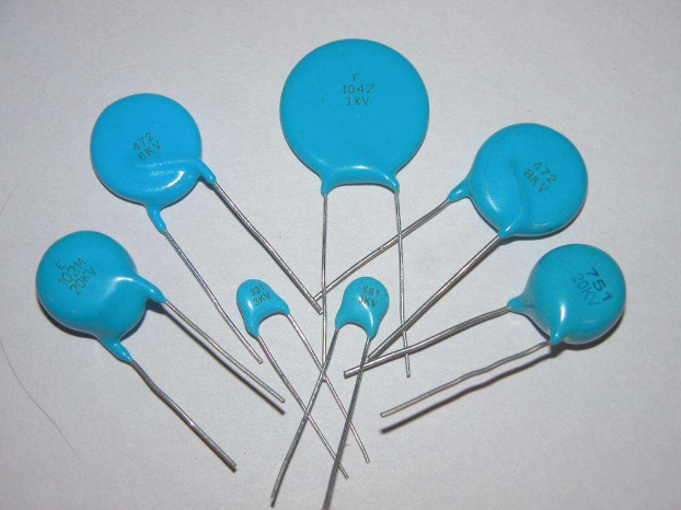
(4) Ceramic capacitors. Ceramic capacitors are the capacitors that we use most in actual circuits, and their structure is relatively simple, that is, the ceramic chips are alternately stacked together and sintered. Small size and low cost, widely used. As long as its characteristics are:
a. Small size. The ceramic chip capacitor has a simple structure and the size can be made very small. The ceramic chip capacitors encapsulated in 0402 or even 0201 are widely used in places with strict size requirements such as mobile phones;
b. The electrical performance is stable and the temperature effect is small;
c. The ESR and ESL values ​​are very low, and the self-resonant frequency is high, which can be applied to the filtering requirements of several MHz to 1 GHz on the PCB;
d. Due to the structural characteristics of multiple layers and packaging reasons, the resistance to bending is poor, and the bending deformation of the PCB may cause the capacitor to crack and fail.
According to the characteristics of the above devices, in addition to the filtering scene, ceramic capacitors are also widely used in DC blocking, coupling, bypass and other applications. Its operating frequency is much higher than that of electrolytic capacitors, and can meet the application environment of several MHz to 1 GHz.
pen usb stick customized,promotional pen usb flash drive,custom flash drive pens,ballpoint pen with usb flash drive,Pen with USB drive and laser pointer
Shenzhen Konchang Electronic Technology Co.,Ltd , https://www.konchang.com