There are two types of DCDC power supplies, one is isolation and the other is non-isolation type. Isolated DCDC means that the output GND has nothing to do with the input GND, and it also becomes a floating power supply. Most common DC-DC chips are non-isolated. The isolated power supply is bidirectional, also known as boost-buck type, non-isolated type, divided into boost and buck.
First of all, let's talk about the non-isolated DC-DC principle. This type of power supply is divided into boost and buck, which are boost and buck modes. First analyze the DCDC step-down circuit:

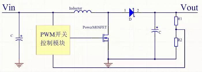
Buck mode DCDC structure is mainly composed of input capacitor, power MOS tube, PWM module, Schottky diode, power inductor, output capacitor and output adjustment resistor. The structure mode of DCDC switching power supply determines that its output noise is relatively large.
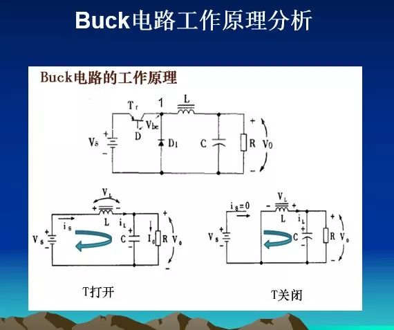
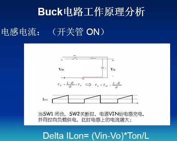
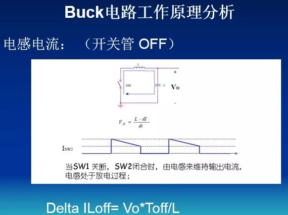
Next, we analyze the working principle. When the power MOS (hereinafter referred to as the switch) is closed, the power supply supplies power to the load through the inductor and stores the energy in the inductor L and the output capacitor. Due to the self-inductance of the inductor L, when the switch is closed , The current increases slowly, that is, the output cannot immediately reach the voltage value of the power supply. After a certain period of time, the switch is turned off. Due to the self-inductance effect of the inductor L (it can be imagined that the current in the inductor has an inertial effect), the current in the circuit will be kept unchanged, that is, the flow continues from left to right. The current flows through the load, returns from ground, flows to the anode of the Schottky diode, and returns to the left end of the inductor L through the diode, thereby forming a loop. The output voltage can be controlled by controlling the duty cycle of PWM.
During the closing of the switch, the inductor stores energy and releases the energy during the opening, so the inductance L is called the storage inductor, and the diode is responsible for providing a current path for L during the opening of the switch, so the diode is called the freewheeling diode. When the switch is closed, the voltage is very small, so the heating power U * I will be very small, which is the reason for the high efficiency of the switching power supply.
Through this principle, we know why when designing DCDC, the output must have a large capacitor, and why the diode and inductor must be close to the IC. And the post-stage filtering of DCDC must be good, because there is a switching frequency inside. Next, I will explain the boost DCDC circuit:
The basic model is as shown above. After our principle analysis of the buck circuit, it should be clear to BOOST. Similarly, adjust the PWM duty cycle to adjust the output. When the PWM duty cycle is 50%, the output voltage is the input voltage 2 times, the basic principle is as follows:
When the switch is turned on, the input voltage flows to the inductor, the inductor current increases linearly, the inductor energy storage increases, and the power source transfers energy to the inductor.
When the switch is open, the inductor voltage is equal to the input voltage minus the output capacitor voltage, the inductor current decreases, the inductor energy storage decreases, and the inductor energy storage transfers electrical energy to the load.
DCDC boost is achieved through such continuous switching, but the current obtained by this structure is relatively small, usually in the hundreds of milliamperes, and the efficiency is not high.

2 in1 Handheld Stick Rechargeable Vacuum Cleaner
2 In 1 Vacuum Cleaner,2 In 1 Stick Vacuum Cleaner,2 In 1 Cordless Vacuum Cleaner,Rechargeable Stick Vacuum Cleaner
Ningbo ATAP Electric Appliance Co.,Ltd , https://www.atap-airfryer.com