The automatic tool changer is an important actuator of the machining center. It is available in various forms, and the following are common.
1. Rotary tool holders Rotary tool holders for CNC machine tools are the simplest automatic tool changers. There are four-way tool holders and hexagonal tool holders, that is, four, six or more tools are mounted on them.
The rotary tool holder must have good strength and rigidity to withstand the cutting force of roughing: at the same time, ensure the repeated positioning accuracy of the rotary tool holder in each indexing.
Figure 1 shows the CNC turning lathe turret, which is suitable for the processing of disc parts. When machining shaft parts, a square turning tool holder can be used. Since the bottom mounting dimensions are the same, it is very convenient to replace the tool holder.
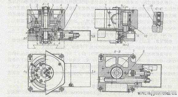
Figure 1 CNC lathe hex rotary tool holder
1-piston 2-turret body 3, 7-gear 4-ring 5-empty gear
6-Piston 8 - Rack 9 - Fixed Pin 10, 11 - Pusher 12 - The entire action of the contact rotary tool holder is controlled by the hydraulic system through the electromagnetic reversing valve and the sequence valve. Its action is divided into 4 steps:
(1) Tool holder lifting When the numerical control device issues a tool change command, the pressure oil enters the lower chamber of the compression hydraulic cylinder from the a hole, the piston 1 rises, and the tool holder body 2 is lifted, so that the movable pin 10 for positioning is fixed. The latch 9 is disengaged. At the same time, the end tooth clutch at the lower end of the piston rod is combined with the idler gear 5.
(2) Tool holder indexing When the tool holder is lifted, the pressure oil enters the left cavity of the indexing hydraulic cylinder from the c hole, and the piston 6 moves to the right. The rack 8 drives the rack 8 to move, so that the idler gear 5 is counterclockwise. The direction is rotated. The tool holder is rotated through 60o by the end tooth clutch. The stroke of the piston should be equal to 1/6 of the circumference of the gear 5 division and controlled by the limit switch.
(3) After the tool holder is pressed and the tool holder is indexed, the pressure oil enters the upper chamber of the pressing hydraulic cylinder from the b hole, and the piston 1 drives the tool holder body 2 to descend. The chassis 3 of the gear 3 is accurately mounted with six cylindrical fixing pins 9 with wedges, and the movable pin 10 is used to eliminate the gap between the positioning pins and the holes to achieve reverse positioning. When the tool holder body 2 is lowered, the movable pin 10 is clamped to the other fixed pin 9, and the gear 3 is in contact with the tapered surface of the ring gear 4, and the tool holder is positioned and clamped at a new position. At this time, the end tooth clutch is disengaged from the idler gear 5.
(4) After the hydraulic cylinder of the indexing cylinder is pressed, the pressure oil enters the right chamber of the indexing cylinder from the d hole, and the piston 6 drives the rack to be reset. Since the end tooth clutch has been disengaged, the rack drives the gear 3 Idle on the axis.
If the positioning and clamping action is normal, the push rod 11 is in contact with the corresponding contact 12, and a signal is sent indicating that the tool change process has ended, and the cutting process can be continued.
In addition to hydraulic cylinder indexing and positioning pin positioning, the rotary tool holder can also be driven by a motor to drive the clutch, as well as other indexing and positioning mechanisms.
2. Replacing the spindle head change tool In a CNC machine tool with a rotary tool, replacing the spindle head is a simple tool change method. The spindle head usually has two types, horizontal and vertical, and the turret is often used to change the spindle head to achieve automatic tool change. On each spindle head of the turret, the rotary cutter required for each process is pre-installed. When the tool change command is issued, each spindle head is sequentially turned to the machining position, and the spindle motion is turned on, so that the corresponding spindle drives the cutter to rotate, and the other spindles in the unmachined position are disengaged from the main motion.
Figure 8-18 shows the horizontal eight-axis turret head. Eight spindles 7 of identical construction are radially distributed on the turret head, and the rotary motion of the spindle is input by the gear 12. When the numerical control device issues a tool change command, the moving gear 3 is first disengaged from the gear 12 by the hydraulic fork, and the pressure oil is supplied to the upper chamber of the center hydraulic cylinder 14. Since the piston rod and the piston 15 are fixed to the base, the center cylinder 14 is lifted with the turret holder body 18 supported by the two thrust bearings 17 and 16, and the clutches 2 and 1 are disengaged. Then, the pressure oil enters the indexing hydraulic cylinder, pushes the piston rack, and then rotates the large gear 4 together with the turret tool holder body 18 through the intermediate gear to turn the main shaft of the next process to the working position. After the end of the indexing, the pressurized oil enters the lower chamber of the central hydraulic cylinder 14, causing the turret head to descend and the clutches 2 and 1 to re-engage, achieving precise positioning. Under the action of the pressure oil, the turret head is pressed and the indexing cylinder is returned to its original position. Finally, the gear 3 is moved by the hydraulic shift fork to engage the newly replaced mainshaft gear 12. In order to improve the assembly processability of the spindle structure, the entire spindle component is housed in the sleeve 5, and the entire component can be withdrawn as long as the screw 10 is removed. The spindle front bearing 9 adopts a tapered double row cylindrical roller bearing. When adjusting, the end cover 6 is first removed, and then the nut 8 is tightened to make the inner ring move axially to eliminate the radial clearance of the bearing.
In order to facilitate the removal of the tool in the spindle taper hole, each spindle has a joystick 13, and by pressing the lever, the rod 11 can be pushed by the ramp to eject the tool.
The indexing, positioning and pressing of the turret spindle head is very similar to that of the ratchet disk indexing table, but the structure is more complicated because of the many rotating spindle components distributed on the turret.
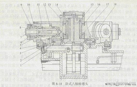
1, 2 a clutch 3, 4, 12 a gear 5 a sleeve 6 end cover 7 a spindle 8 a nut
9, 16, 17 a bearing 10 a screw 1l a push rod 13 a joystick 14 a hydraulic cylinder 15 a piston 18 a turret tool holder body due to space constraints, the structure of the spindle component can not be designed very solid, thus Affects the stiffness of the spindle system. In order to ensure the rigidity of the spindle, the number of spindles must be limited, otherwise the structure size will be greatly increased.
The main advantage of the turret spindle head change mode is the elimination of a series of complicated operations such as automatic loose clamping, unloading, loading, clamping and tool handling. This improves the reliability of the tool change and significantly reduces the tool change time. However, due to the above structural reasons, the turret spindle head is usually only used for machine tools with less procedures and less precise requirements, such as CNC drilling machines.
3. Automatic tool change system with tool magazine The automatic tool change system with tool magazine consists of a tool magazine and a tool change mechanism. Firstly, all the tools that need to be used in the machining process are installed on the standard tool holders. After pre-adjusting the dimensions outside the machine, they are placed in the tool magazine in a certain way. When changing the tool, the tool is selected in the tool magazine, and the tool is removed from the tool magazine and the spindle by the tool changer. After the tool is exchanged, the new tool is loaded into the spindle and the old tool is returned to the tool magazine. The magazine that stores the tool has a large capacity. It can be mounted on the side or above the headstock, or it can be installed as a separate component outside the machine and transported by the handling device.
Compared with the turret spindle head, since the automatic tool changer with the tool magazine has only one spindle in the spindle head of the CNC machine tool, it is possible to design the spindle component to fully enhance its rigidity, thus meeting the requirements of precision machining. In addition, the tool magazine can store a large number of tools, thus enabling multi-process machining of complex parts, which significantly improves the adaptability and processing efficiency of the machine tool. Therefore, the automatic tool changer with tool magazine is especially suitable for CNC drilling machines, CNC milling machines and CNC boring machines.
The tool magazine is the main component of the automatic tool changer. Its capacity, layout and specific structure have a great influence on the design of CNC machine tools.
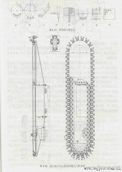
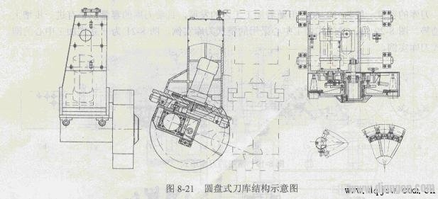
The magazine can be designed in a variety of forms depending on the capacity required for the magazine and the way the knife is taken. Figure 8-19 lists the most commonly used ones. Figure 8-19a~d is a single-disc tool magazine. To adapt to the layout of the machine tool spindle, the tool axis of the tool magazine can be configured in different directions (as shown in Figure 8-19a~c). Figure 8-19d is the tool can be used for 90o. The inverted disc magazine has a structure that simplifies the picking action. The single-disc tool magazine has a simple structure, and the capacity of the tool magazine is usually 15 to 30. It is convenient to take the knife, so it is the most widely used. Figure 8-19e is a drum magazine type (also known as a hedgehog) tool magazine. Its structure is very compact. In the same space, its tool magazine has a large capacity, but the action of selecting a knife and taking a knife is complicated. Figure 8-19f is a chain tool magazine with a large flexibility and a large number of stored tools. The tool selection and tool removal are very simple. When the chain is long, the number of support sprocket wheels can be increased, and the chain can be folded back, which improves the utilization of space. Figures 8-19g and 8-19h are multi-disc and lattice-type tool magazines respectively. Although they also have compact structure, the selection and knife-taking actions are complicated and less applicable. The capacity of the tool magazine is generally 10~60, but with the development of the processing technology, the capacity of the tool magazine seems to have a further increase trend. Figure 8-20 shows an example of a chain magazine used in a gantry machining center, and Figure 8-21 shows an example of a disc magazine in a vertical machining center.
8.4.3 Tool changer The tool change mode of CNC machine tools is usually divided into two types: tool exchange by the relative movement of the tool magazine and the machine tool spindle and tool exchange by the robot. The way in which the tools are exchanged and their specific structure have a direct impact on the productivity and operational reliability of the machine.
The tool exchange device is realized by the relative movement between the tool magazine and the machine tool spindle. When the tool change is performed, the used tool must be sent back to the tool magazine, and then the new tool is taken out from the tool magazine. These two actions cannot be performed simultaneously. Therefore, the tool change time is long. The gantry machining center shown in Figure 8-20 is an example of this type of tool exchange. Its tool selection movement is performed by the servo motor driving the chain magazine rotation, and the tool change movement is performed by the spindle box moving along the Y and Z axes.
The use of robots for tool exchange is the most widely used because of the flexibility of the robot tool change and the reduced tool change time. At present, most of the machining centers use the memory type of optional tool change. In this way, the tool number can be stored in the PC of the CNC system corresponding to the tool holder position (address) in the magazine, and its trace is always remembered regardless of the tool holder. A position detection device (generally mounted with the motor) is mounted on the magazine to detect the position of each pocket so that the tool can be removed and returned. There is also a mechanical origin on the magazine, so that each time the knife is selected, it is selected nearby. For the disc magazine, the movement of the knife or the forward or reverse rotation will not exceed 180o.
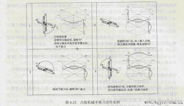
Figure 8-22 shows the structure of the cam manipulator tool change, and Figure 8-23 shows an example of the cam manipulator tool change action.
The structure of the tool magazine and the tool changer is complicated, and it moves frequently during the work, so the failure rate is high. At present, more than 50% of the faults on the machine tool are related to it. If the tool magazine is in motion failure, the positioning error is too large, the manipulator grip is unstable, and the manipulator movement error is too large. At the end of these faults, the tool change position is caused, and the whole machine stops working. Therefore, the maintenance of the tool magazine and the tool changer is very important.
1. Maintenance points of the tool magazine and tool changer
1) It is strictly forbidden to load overweight and long tools into the tool magazine to prevent the knife from falling or the tool colliding with the workpiece and fixture when the robot is changing the tool.
2) The sequential tool selection method must pay attention to the correct order of the tools placed in the tool magazine. Other tool selection methods must also pay attention to whether the changed tool is consistent with the required tool, and prevent accidents caused by incorrect tool cutting.
3) When loading the tool into the tool magazine manually, make sure it is in place, securely fastened, and check that the locking device on the tool holder is reliable.
4) Always check whether the zero return position of the tool magazine is correct, check whether the position of the machine tool spindle return point is in place, and find that the problem should be adjusted in time, otherwise the tool change action cannot be completed.
5) Pay attention to keep the tool holder and the knife sleeve clean.
6) When starting the machine, the tool magazine and the robot should be run empty to check whether the work of each part is normal, especially if the travel switch and solenoid valve can operate normally. Check whether the pressure of the hydraulic system of the robot is normal, whether the tool is securely locked on the robot, and if it is abnormal, it should be handled in time.
2. The main faults of the faulty tool magazine of the tool magazine are: the tool magazine cannot rotate or the rotation is not in place; the knife sleeve cannot clamp the tool; the knife sleeve is not up and down.
(1) The tool magazine cannot be rotated or rotated. The reason why the tool magazine cannot be rotated may be: 1 The coupling of the motor shaft and the worm shaft is loose; 2 If the inverter is faulty, check whether the input and output voltage of the inverter are normal; 3plc has no control output, it may be the relay failure in the interface board; 4 mechanical connection is too tight; 5 grid voltage is too low.
The reason why the tool magazine is not in place may be: motor rotation failure, transmission mechanism error.
(2) The tool holder cannot clamp the tool. The reason may be that the adjusting screw on the knife sleeve is loose, or the spring is too loose, resulting in insufficient clamping force; or the tool is overweight.
(3) The reason why the knife sleeve is not up and down is that the adjustment of the device is improper or the machining error is too large, resulting in incorrect position of the fork; the limit switch is incorrectly installed or improperly adjusted, resulting in a feedback signal error.
3. Tool changer failure
(1) The tool holder does not tighten the knife. The reason may be that the clamping claw spring pressure is too small; or the nut behind the spring is loose; or the tool is overweight; or the robot clamping lock does not work.
(2) The reason why the tool can not be loosened after clamping may be that the spring of the loose lock is too tight, and the claw cannot be retracted: the nut should be loosened so that the maximum load does not exceed the rated value.
(3) When the tool is exchanged, the spindle box does not return to the tool change point or the tool change point drifts when the knife is changed. If the robot does not get in place when the knife is caught, the tool will start to be pulled, which will cause the knife to be lost when the tool is changed. At this time, the headstock should be moved back to the position of the tool change point and the tool change point should be reset.
Second, 10 cases of automatic tool changer failure maintenance
1. Maintenance example of robot failure 1. Fault phenomenon: A machining center uses a cam manipulator to change the tool. The structure of the manipulator and the tool change procedure are shown in Figure 2-22 and Figure 2-23. During the tool change process, the action is interrupted and the 2035# alarm is issued. The display content: the robot is out of fault.
Analysis and processing: According to the alarm content, the machine is unable to execute the next step "Pull the tool from the spindle and the magazine", and the tool change process is interrupted and alarmed.
The robot failed to reach out and pulled out the tool from the spindle and the magazine. The cause of the failure may be:
(1) "loose knife" sensor switch failure In the process of tool change, the completion signal of each action is sent by the sensor switch, and the next action can only be performed after the previous action is completed. The third step is “spindle loosening knifeâ€. If the sensor switch does not signal, the robot “pull the knife†will not move. Check the two sensor switches and the signal is normal.
(2) The “loose knife†of the “loose knife†solenoid valve failure spindle is completed by the solenoid valve turning on the hydraulic cylinder. If the solenoid valve fails, the hydraulic cylinder will not enter the oil and the tool will be “looseâ€. Check that the spindle's "loose knife" solenoid valve is operating normally.
(3) The “loose knife†hydraulic cylinder does not operate due to insufficient pressure or oil leakage in the hydraulic system, or the stroke is not in place to check the cutter cylinder hydraulic cylinder, the action is normal, the stroke is in place; open the headstock (Fig. 8-2) rear cover Check the spindle loose-knife hydraulic cylinder and find that it has reached the position of the loose knife, the oil pressure is also normal, and the hydraulic cylinder has no oil leakage.
(4) There is a problem with the manipulator system. The reason for not being able to establish the "pull extraction" condition may be that there is a problem with the motor control circuit. Check that the motor control circuitry is normal.
(5) Schematic diagram of the spindle system The schematic diagram of the spindle structure is shown in Figure 8-2. The cutter is to pull the pull rod at the end of the tool handle by the disc spring through the pull rod and the spring chuck; when the knife is loosened, the piston rod of the hydraulic cylinder presses the top rod, and the top rod pushes the pull rod through the hollow screw, and on the other hand, the spring chuck Loosen the pull stud of the tool and push the pull stud on the other hand to make the tool move to the right and become "loose" in the taper hole of the spindle.
The reason why the spindle system is not loosened is estimated to have the following four points: 1 the length of the tool tail pull pin is not enough, so that the hydraulic cylinder has moved into position, but the tool top has not been loosened; 2 the position of the hollow screw at the tail of the pull rod has changed. The hydraulic cylinder stroke can not meet the requirements of the "loose knife"; 3 the top rod has a problem, has been deformed or worn; 4 the spring chuck has failed, can not be opened: 5 spindle assembly adjustment, the tool movement amount is adjusted too small, As a result, some comprehensive factors in the use process can not meet the "loose knife" condition.
Treatment method: Remove the “loose knife†hydraulic cylinder and check that the fault is the adjustment of the “stretching amount†of the hollow screw when the assembly is assembled. Therefore, the “loose knife†hydraulic cylinder stroke is in place, and the tool is in the spindle. The "pressing out" in the taper hole is not enough and the tool cannot be taken out. Adjust the "stretching amount" of the cannulated screw to ensure that the amount of extrusion of the shank in the spindle taper hole is 0.4~0.5mm after the stroke of the spindle "loose knife" hydraulic cylinder is in place. After the above adjustments, the troubleshooting is eliminated.
Example 2. Fault phenomenon: JCS-018A vertical machining center (produced by Beijing Precision Machine Tool Factory) is out of order; arm rotation speed is uneven, gas-liquid converter loses oil frequency, robot rotation is not in place, arm lift does not move, or arm reset is not spirit. Adjusting the SC-15 throttle valve with manual adjustment can only maintain normal operation for a short period of time, and the exhaust sound is gradually turbid, not as clear as normal operation, and finally can not be changed.
Analysis and processing:
1) The arm rotates 75o to grasp the tool on the spindle and the knife sleeve, and must be grasped in place to lower the knife. After the action is in place, the rotation is 180o, the tool change position is increased, the knife is inserted, the arm is reset, and the knife sleeve is placed. The arm is rotated 75o and 180o. The power transmission is compressed air source. The gas-to-liquid converter is converted into hydraulic oil. The rotation speed is controlled by the SC-15 throttle valve. The reversing is controlled by the 5ED-IONl8F solenoid valve. . In general, these components have a long life and can eliminate the problems of such components.
2) Because the upper and lower sides of the knife sleeve and the upper and lower arms are independent of the air source, the exhaust is also an independent sound-absorbing exhaust port, so it is not affected by the transmission of the arm's rotational force; but when the rotation is not in place, the arm lifting is impossible. According to this principle, it is necessary to focus on checking the arm rotation system to execute the components.
3) Observing the 75o, 180o arm rotation or non-rotation, the hydraulic cylinder expansion and contraction corresponding to the gas-liquid conversion of each oil standard lifting, high and low conditions, the left and right paired gas-liquid converter, the left side of the upper limit to the lower limit, and vice versa, and The common exhaust port has a large amount of oil discharged. The analysis of the gas-liquid converter and the nylon pipe are all closed installation, so the cause of the failure should be on the actuator hydraulic cylinder.
4) Disassemble the hydraulic cylinder of the manipulator and disassemble it. It is found that the O-ring of the piston support ring has linear wear and can not be sealed. The inner wall of the hydraulic cylinder is rough, the annular knife pattern is obvious, and the precision is too poor. Replace the 80-cylinder cylinder produced by Beijing Precision Machine Tool Plant. After the reloading adjustment, the fault disappeared. It has been in normal operation for 7 years, and no mechanical tool change failure has occurred.
Example 3. Fault phenomenon: A BX-110P machining center equipped with FANUC 11 system, when the JOG mode is used, the robot can not shrink the claw when picking up the tool. When the machine tool is machining the workpiece in the JOG state, the robot takes the tool out of the main tool magazine and feeds it into the knife feed box. It does not shrink the claws, but does not alarm; the mode is selected to the ATC state, and the manual operation is normal.
Analysis and processing: After viewing the ladder diagram, the original limit switch LS916 is not pressed; after adjusting the position of the limit switch, the machine returns to normal. However, after a while, the fault occurred again, and the LS916 was not loosened, but it was not pressed, and it was suspected that the manipulator's hydraulic cylinder rod did not reach into position. After checking, it was found that the set screw of the top lock nut of the hydraulic cylinder rod was loose, and the stroke of the hydraulic cylinder was changed. After the lock nut was adjusted and the set screw was tightened, the fault was eliminated.
Example 4. Fault repair failure phenomenon in which the tool change is not in place: the tool chain is not in operation when the tool is automatically changed. When the automatic tool change program is executed, the magazine starts to run, but the tool that needs to be changed does not have the drive in place, and the magazine stops. The machine automatically alarms after 3 minutes.
Analysis and processing: The MPA-H100A machining center is produced by Mitsubishi Corporation of Hiroshima, Japan. The CNC system is FANUC 6M-MODELB, and the workbench is 1000mm×l000mm with 60 tools. It is known from the above fault detection alarm that the tool change time is exceeded. At this time, in the MDI mode, the magazine does not operate regardless of whether the tool magazine is manually rotated clockwise or counterclockwise. Check the electrical control system, no abnormalities were found; the LED on the PLC output indicator burned, indicating that the PLC has output, and the counterclockwise LED on the counterclockwise and counterclockwise solenoid valve is illuminated, indicating electromagnetic The valve has electricity and the magazine does not operate at this time, so the problem should occur in the hydraulic system or other aspects. However, the pressure of the hydraulic system is normal, and the oil passages are unblocked and there is no blockage; no problems are found in checking the hydraulic devices of the various hydraulic valves. It is estimated that the fault may be caused by the hydraulic motor. To this end, the protective cover was removed, the hydraulic motor was removed, the parts that could be disassembled were inspected, and no problems were found; after that, the hydraulic motor was sent to the Dalian Combined Machine Tool Research Institute for identification. The hydraulic motor is intact. After careful analysis and research, the comrades present believe that there can only be one problem, that is, mechanical failure; however, there are no obvious damage marks in all parts of the tool magazine, so mechanical damage failure can be excluded; The problem comes down to the fact that the load on the magazine is too heavy, or there is a blockage, so that the hydraulic motor does not move.
In fact, it is. When we machine the 10t forklift box, due to the complexity of the workpiece, the machining surface is more, the tool used is more than 40, and the large tool, the long tool (the longest tool reaches 550mm), the heavy tool (the heaviest The tool is more than 25kg). The amount of the tool is very large, and we ignore the distribution of the tool on the tool magazine. The heavy tool is not evenly distributed on the tool magazine, but is concentrated in a section, so as to cause the chain of the tool magazine. The local tension is too tight, the deformation is large, and there may be blockage, so the hydraulic motor of the machine does not move. Finally, we loosened the adjustable part of the chain of the magazine, and everything returned to normal, indicating that the problem is indeed on the machine.
Note: The chain of the magazine can't be adjusted too loose, otherwise there will be danger of "flying knife". When the robot grabbed the knife on the side of the magazine, when the tool was pulled out, then raised, and then rotated 180o, the tool was suddenly thrown out, which caused a big disaster. The reason for this failure is because the chain of the magazine is too loose. The two jaws of the machine manipulator are pushed outward by the outward force of the shank by the downward thrust, and then the tool is clamped by the tension of the spring. When the robot grabs the knife downward, the chain belt is also bent downwards with the downward thrust of the manipulator because the chain is too loose. As a result, the claw of the robot only grasps more than half of the handle, and does not fully grasp, Grasp the grip, when the robot rotates, because the tool is heavy, under the action of centrifugal force, the tool will smash out in the tangential direction. After a little tightening of the chain, no similar situation happened.
Maintenance experience: There are two types of drive systems for the tool magazine, one is mechanical transmission and the other is hydraulic transmission. The MPA-H100A machining center is a product in the early 1980s. It uses hydraulic transmission, that is, hydraulic motor, solenoid valve, flow control valve, etc. to drive the operation of the tool magazine. Compared with the tool magazine driven by the variable frequency speed control motor, it is much simpler and more intuitive in terms of its electrical control system, and generally is not prone to failure. But it also varies with the environment in which the equipment is used, the processing conditions, the complexity of the workpiece, and the number of tools used, especially the length of the tool, the weight of the tool, and the distribution of the tool in the tool magazine. These are faults. Possible factors.
Maintenance example of rotary tool post failure 5. Fault phenomenon: The motor of the SAG210/2NC CNC lathe tool holder does not move, and the tool holder cannot move.
Analysis and processing: SAG210/2NC and CKD6140 and CNC lathe, the matching tool holder is LD4-I four-station electric tool holder.
Analysis of the cause of the fault may be that the motor phase sequence is reversed or the power supply voltage is low, but the motor armature line and the power supply voltage are adjusted, and the fault cannot be eliminated. Indicates that the fault is caused by a mechanical cause. Remove the motor cover and rotate the motor blades to find that the resistance is too large. Further inspection of the motor was found, the worm bearing was damaged, and the motor shaft and the worm clutch were of poor quality, causing resistance to the motor.
Replace the bearing, repair the clutch, and troubleshoot.
Example 6. Fault phenomenon: The upper body of the SAG210/2NC CNC lathe tool holder is lifted but not rotated.
Analysis and treatment process: The tool holder of the lathe is the same as the above example. According to the mechanical principle analysis of the electric tool holder, the upper body cannot be rotated, and the coarse positioning pin may be stuck or broken in the tapered hole. After removing the electric tool holder and replacing the new positioning pin, the upper body still cannot be rotated into position. When re-disassembling, it is found that when assembling the cutter body, it should be aligned with the four sides of the lower cutter body, and the cutter disc must be engaged. After assembly according to the above requirements, the fault is eliminated.
Example 7. Fault phenomenon: The positioning of the Hungarian EEN-400 CNC lathe tool holder is not allowed.
Analysis and processing: The EEN-400 CNC lathe is produced by SEIN, Hungary. The tool holder is made in Bulgaria and can hold 6 knives. The main reason for the inaccurate positioning is that the mechanical wear of the tool holder is more serious, and it can not be solved by means of conventional adjustment and tool compensation clearance compensation. It is necessary to consider the overall replacement. It is understood that domestic CNC tool holder manufacturers have been able to produce horizontal 6-position tool holders of the same performance and can be used for proper processing.
After replacing the original tool holder with the JYY horizontal CNC electric tool holder produced by the Shaanxi Provincial Machinery Research Institute, the positioning accuracy was restored. After more than a year of use, it has been normal.
Example 8. Faulty maintenance failure phenomenon of out-of-control processing: The processing size of Nanjing JN series CNC system cannot be controlled.
Analysis and processing: The machine tool is an economical CNC lathe modified by the JN series machine tool numerical control system of Nanjing Jiangnan Machine Tool Numerical Control Engineering Co., Ltd. The tool holder is LD4-I electric tool holder.
In the process of product processing, the machine tool can not control the processing size. After the operator modifies the parameters in the system, the size of the digital display display is very different from the actual processed size, and the size changes irregularly. It can be found that even if the processing parameters of the system are not modified, the size of the processed product is constantly changing. Since the machine is mainly for bore machining, the dimensional change is mainly reflected on the X-axis. In order to determine the fault location, the replacement method is used to exchange the X-axis drive signal with the Z-axis drive signal, that is, the 2-axis control signal is used to drive the X-axis, and the X-axis control signal is used to drive the Z-axis. After the replacement, the fault still exists. This indicates that the X-axis drive signal is fault-free. It also indicates that the fault source should be on the X-axis stepper motor and its transmission mechanism, ball screw and other hardware.
Check that the above-mentioned transmission mechanism, ball screw and other hardware are fault-free, and further check the X-axis axial repeat positioning accuracy is also within its technical specifications. What is the reason why the X-axis machining size cannot be controlled? Thinking about checking and analyzing the fault, I found that an important component, the electric tool holder, was neglected in the analysis and inspection.
Check the repeat positioning accuracy of each tool number of the electric tool holder and find that the electric tool holder is not positioned correctly. The reason for the inaccurate positioning of the electric tool holder is analyzed. If the mechanical positioning of the electric tool holder itself is not accurate, the fault should be fixed. There should be no phenomenon that the machining size cannot be controlled. There are other reasons for this failure phenomenon. Check the rotation of the electric tool holder and find that when the electric tool holder is lifted, an iron chip is stuck inside. Iron filings make the positioning inaccurate, which is the source of the fault.
Disassemble the electric tool holder, use the compressed air to blow off the iron scraps on the electric knife holder positioning tooth plate, and re-assemble the electric tool holder to solve the problem.
example. Fault repair that cannot be rotated by the magazine
Example 9. Fault phenomenon: The chain is not running properly when the tool is automatically changed. When the automatic tool change program is executed, the magazine starts to run, but the tool that needs to be changed does not have the drive in place, and the magazine stops. The machine automatically alarms after 3 minutes.
Analysis and processing: The chain tool magazine used in the TH42160 gantry machining center is shown in Figure 8-20. The supporting CNC system is SIEMENS 840D.
It is known from the above fault detection alarm that the tool change time is exceeded. At this time, in the MDI mode, the magazine does not operate regardless of whether the tool magazine is manually rotated clockwise or counterclockwise. Check the electrical control system, no abnormalities found; the LED on the PLC output indicator is lit, indicating that the PLC has output, then the problem should occur in mechanical transmission. It is estimated that the fault may be on the reducer. To this end, the protective cover was removed, the servo motor was removed, and the reducer was disassembled. It was found that the coupling key on a drive shaft in the reducer was detached, causing the power transmission route to be interrupted and the tool magazine could not be rotated. After repairing the gear unit, troubleshoot.
Example 10. Fault phenomenon: When the tool change is not in place when the tool is changed automatically, the tool magazine stops running and the machine automatically alarms.
Analysis and processing: The chain tool magazine used in the TH42160 gantry machining center is shown in Figure 8-20. The supporting CNC system is SIEMENS 840D.
It is known from the above fault detection alarm that the servo motor of the magazine is overloaded. Check the electrical control system, no abnormalities are found, the problem should occur in mechanical transmission or other aspects: 1 There is a foreign object stuck in the chain of the tool magazine or the reducer: 2 The tool on the chain of the tool magazine is too heavy: 3 Poor lubrication: After checking the above Three items are normal. When the servo motor was removed, it was found that there was a lot of cutting fluid inside the servo motor, which caused the coil to be short-circuited. The reason for the observation is that the seal ring at the junction of the motor and the reducer wears, causing the cutting fluid to penetrate into the motor. After replacing the seal and servo motor, troubleshoot.
Micro switches
Micro switches, as the name suggests, use very small force switches. It is the switch that the external mechanical force acts on the moving reed through the transmission element, and the fixed contact and the moving contact at the end of the driving reed are quickly turned on or off. There are small, ultra-small, super-small and so on in size. Functionally waterproof. Furthermore, Metal Switches, Automotive Switches, Push Button Switches are also our competitive products.
This Mini Micro Switches are used for automatic control and safety protection in devices that need frequent switching circuits. They are widely used in electronic equipment, instrumentation, mining, power systems, household appliances, electrical equipment, and aerospace, aviation, ships, missiles, and so on. Tanks and other military fields have been widely used in the above fields. The switch is small, but it plays an irreplaceable role.

There are many kinds of Waterproof Micro Switches, and there are hundreds of internal structures. There are common type, small size and super small size according to the volume. According to the protective performance points, there are waterproof type, dust-proof type, and explosion proof type; according to the dividing form, there are Single type, double type, multiple type.
The Electric Micro Switches, has a small contact spacing and a quick acting mechanism, and the contact mechanism that performs the switching action with a prescribed stroke and force is covered by the outer casing, and has an external actuator and a small outer shape.

Micro Switches,Waterproof Micro Switches,Mini Micro Switch,Metal Micro Switch
YESWITCH ELECTRONICS CO., LTD. , https://www.yeswitches.com