0 Preface
With the rapid development of technology, more and more machines and field operations tend to use human-machine interfaces, and the powerful functions and complex data processing of PLC controllers also require a man-machine that is easy to operate and has a simple function. interface. The emergence of the touch screen is undoubtedly a huge innovation in the field of automation in the 21st century. The combination of touch screen and PLC has become the dominant form.
PLC is a new type of control element with simple structure, good versatility and complete functions. Its main advantage is its strong anti-interference ability, which can improve the reliability and stability of the system and production efficiency, especially suitable for industrial control.
The touch screen is a human-machine interface that connects people and machines. It replaces the original console and display. It can be used for data display and parameter setting, and can describe the control process of the system in the form of dynamic curves. It expands the functions of the PLC. Reduce the use of instruments such as buttons, switches, and meters.
1 system composition
The system uses a system consisting of Siemens S7-200 and Devin touch screen to control the on-site electric valve, solenoid valve, motor and temperature controller. The S7-200 collects the temperature and pressure signals of the site through the analog input module and the temperature and pressure sensors. The signal is transmitted to the touch screen through A/D conversion and numerical conversion on the PLC. The touch screen displays the real-time temperature value, pressure value and temperature curve. , pressure curve and PID curve; and PID parameters can be set through the touch screen, the touch screen sends instructions to the PLC to control the on-site actuator. Since the PLC interface is RS-485 and the touch screen interface is RS-232, an RS-485 / RS-232 conversion line is required. The composition of the control system is shown in Figure 1.
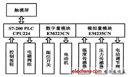
Figure 1 Control system composition block diagram
2 PLC and touch screen communication
The data transfer between the computer and the computer or between the computer and the terminal can be carried out in two ways: serial communication and parallel communication. The communication of S7-200 series PLC is divided into three working modes: PPI communication mode, free port communication mode and Profibus-DP communication mode. This system adopts free port communication mode.
2.1 PLC free port communication
When is S7? ? When the 200 series PLC uses free port communication, the data transmission protocol is completely determined by the user program, and all communication tasks are programmed by the user. Through the free port mode, the S7-200 can communicate with serial printers, bar code readers, and touch screens with baud rates ranging from 1 200 to 115 200 bit / s (adjustable). The core of free port communication is the two instructions XMT (send) and RCV (receive) and the corresponding special register control. The free port communication of this system uses free port 0, and the S7-200 CPU uses SMB30 to define the working mode of free port 0. The selection of the check, the data bits of each character, the baud rate of the free port, and the protocol selection can be set by the special register SMB30. The free port interface on the S7-200 CPU is RS-485, and the interface on the touch screen is RS? ? 232, design needs to make an RS-485 / RS-232 communication line. The communication port RS-485 of the S7-200 CPU is a half-duplex communication port. The transmit and receive commands cannot be activated at the same time. In this case, the RCV (receive) can be controlled by controlling the special register SMB87, when the PLC is within the specified time. When no message is received, the RCV instruction will stop receiving.
2. 2 Touch screen data transmission method
The serial data frame structure of the Diwen touch screen consists of four data blocks: the frame header, the instruction, the data, and the end of the frame. The frame header is fixed to 0XAA, and the instruction refers to the Divin instruction set. The data is at most 249 B, and the end-of-frame end is fixed to 0XCC, 0X33, 0XC3, and 0X3C. 0X represents a hexadecimal number. All instructions or data on the Divin touch screen are in hexadecimal (HEX) format. For font (2 bytes) data, the byte transfer order is in high byte first transfer (MSB). When the transmission direction is downlink (Tx), the PLC sends data to the touch screen, and the data is input from the “Din pin†of the touch screen serial interface. When the transmission direction is uplink (Rx), the touch screen sends data to the PLC, and the data is from the touch screen serial interface. The "Dout pin" output. The data exchange process between the touch screen and the PLC serial port is shown in Figure 2.
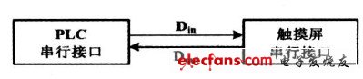
Figure 2 Schematic diagram of the data exchange process
MOSO UFO High Bay LED Driver have the character of high power factor, high efficiency, high reliability and high-precision constant current. The UFO led driver owns a complete of function, various specifications can meet more different parameter of customers` requirement.


MOSO Intelligent innovator UFO shape led power has the led driver industry ' s unique derating over temperature protection circuit , which can make the light power supply not easy suddenly happen the phenomenon of over - temperature and shutdown even under the harsh working environment , so as to ensure continuous illumination.
The efficiency of the led driver supply is high and the power consumption is small. Accordingly, the heat in the lamp is small, then it reduce the temperature rise of the lamp. It is more advantage to delay the light decay of LED.
This Circular high-bay lighting drivers creatively integrated limited power, 0~10V/PWM dimming, dali control is optional.
Dali Industrial Light LED Driver complied with CCC/CE/ENEC/UL/SAA/CB safety regulations. Surge immunity is DM-4KV,CM-6KV.
High Bay LED Driver,Waterproof High Bay LED Driver,Modern High Bay LED Driver,UFO High Bay LED Driver
Moso Electronics , https://www.mosoleddriver.com