Abstract: In order to meet the requirements of RFID readers in different application systems, a handheld RFID reader with embedded Ethernet network interface based on MSP430F149 microcontroller is developed. This paper introduces the network interface design method of the MCU and Ethernet controller RTL8139 in the RFID reader, which realizes the handheld RFID reader to access the Internet for data communication.
RFID technology is currently widely used in identification, anti-counterfeiting applications, supply chain applications, public transportation management, logistics management, production line automation and process control, container identification and other fields. Due to the limited memory capacity of the handheld RFID reader, the data stored in the reader can be transferred to the computer for processing via an interface such as USB, but it is more convenient and quick to transfer the data in the reader to the remote computer. In the system, networking portable devices is one of the effective ways to solve the above problems. However, current handheld RIFD readers do not have a network interface to the Internet. In addition, the handheld RFID reader is powered by the internal battery, so reducing its power consumption is also one of the main problems. The MSP430F149 microcontroller is a 16-bit ultra-low-power processing chip that integrates multiple analog and digital circuit modules of different functions into one, suitable for applications and portable instrumentation that require battery power.
Therefore, the paper mainly introduces the hardware design method of MSP430F149 MCU and Ethernet controller RTL8139 interface in handheld RFID reader, as well as the corresponding hardware device driver design and TCP / IP protocol stack processing method.
1 Network interface hardware structure.
1. 1 network interface
Handheld RFID readers are the main equipment of portable RFID systems. The network interface is mainly composed of MSP430 MCU and Ethernet controller RTL8139. Its network interface hardware structure is shown in Figure 1.
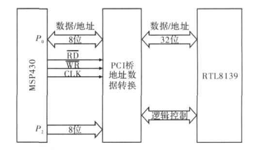
Figure 1 Network interface block diagram
According to the low power requirements of portable devices, MSP430 MCU adopts MSP430F149, which has ultra-low power consumption, powerful processing capability, rich on-chip peripheral modules and various memory formats. Among them, there are 2 8-bit parallel ports P1 with interrupt function. P2 and four 8-bit universal parallel ports P3, P4, P5 and P6 can interface with the Ethernet controller and implement other interface functions of the RFID reader.
The isolation transformer is a PM34 - 1006M10 / 100 / 1000M transformer. The RTL8139 Ethernet controller is used as the network interface.
Since the RTL8139 is a PCI bus interface, it cannot be directly interfaced with an 8-bit MCU and requires a PCI interface for switching. The signals used by the microcontroller for external memory operations are P0, P2, ALE, and RD and WR signals. Among them, P0 port is address (low 8 bits) / data multiplexing, P2 port is high 8-bit address signal; ALE is address latch signal, when it is high level, the value of P0 port is latched to the lower 8-bit data line ; RD and WR are valid signals for reading and writing, active low. Therefore, the PCI interface actually acts as a read-write sequence from the microcontroller to 32-bit PCI read and write timing.
1. 2 RTL8139 structure and programming interface
RTL8139 is a highly integrated IEEE802. 3 standard Ethernet controller chip manufactured by Realtek Corporation of Taiwan, supporting Microsoft's PnP specification. Twisted pair cables can be connected to full-duplex network switches to receive and transmit data simultaneously. Support UTP (Unshielded Twisted Paired), AUI (Attachment Unit Interface) automatic detection. Support IO address full decoding mode. Its main features are as follows:
(1) Complies with Ethernet II and IEEE802. 3 (10Base5, 10Base2, 10BaseT) standards.
(2) Supports two working modes of jumper and jumper-free.
(3) Full-duplex, the transmission and reception can reach the rate of 100 Mbit·s -1 at the same time.
(4) Support for 32-bit data PCI bus.
(5) Allow 3 diagnostic LEDs to be programmable.
(6) 128-pin LQFP package reduces PCB size.
As shown in Figure 2, the RTL8139 already contains the entire network interface layer protocol, so it is simple to apply. The user does not have to consider the link control problem, but only consider how the microcontroller can read the TCP/IP protocol data from the RTL8139.
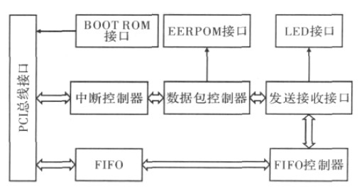
Figure 2 RTL8139AS internal structure diagram
PCI bus signals are 3. 3 V standard and 5 V standard, and there are many signal lines, but not all PCI devices use all PCI interface signals, and only need to use them. The RTL8139AS Ethernet controller follows the 3 V standard and uses only the following parts of the PCI bus signal: AD[31: 0] is the data signal multiplexing bus.
FRAME is the frame period signal, driven by the current master device, indicating the start and duration of an access. IRDY prepares the signal for the master device.
TRDY prepares the signal for the slave device. C /BE enables multiplexing signals for bus commands and byte enable. The address period is a bus command and the data period is byte enabled. IDSEL is the initialization device selection signal. Used as a chip select during parameter configuration read and write transfers. For a PCI device only, it can be tied high. RST is the reset signal. CLK is the system clock signal, the frequency range is DC ~ 33 MHz. The above signals are valid on the rising edge of CLK. INTA is the interrupt request signal, and the RTL8139 data can be used to issue an interrupt to the host controller when it is ready.
The DEVSEL selects a signal for the device, indicating that the device that drives it has become the currently accessed device. Since the RTL8139 is a single PCI device in the system, this signal can be used.
2 network interface software structure
RFID reader system network interface software mainly includes hardware device drivers, TCP / IP protocol stack, application protocols and other user applications. The flow of the network interface software is shown in Figure 3.
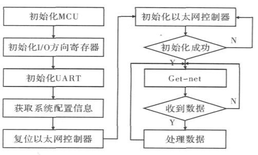
Figure 3 Network interface software flow chart.
The application protocol and other user applications will be designed according to the specific functional requirements of the RFID reader during the secondary development. Here, the hardware device driver and the implementation method of the TCP/IP protocol stack are mainly introduced.
2. 1 hardware device driver
The hardware device driver treats the PCI interface as the external memory of the microcontroller. The microcontroller reads and writes the external interface to read and write the PCI interface. The PCI interface then converts the read and write operation timing into PCI timing to Ethernet controller. Take action. It mainly consists of 3 parts, network initialization, transmission control and reception control. Mainly complete register operations such as CR, TCR, RCR IMR ISR, RBSTART, MAR.
The transmission control process is in the network. The process of frame transmission is that the sender encapsulates the data to be sent into frames according to the frame format requirements, and then sends the data to the transmission line of the network with the network card. The transmission block diagram is shown in Figure 4.
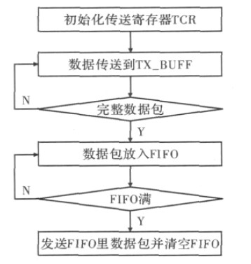
Figure 4 RTL8139 data transmission flow chart.
The receiving control process is divided into 2 steps. The first step is to determine whether the data packet is a local data packet according to the Harmonic algorithm. If yes, the receiving is put into the FIFO. If the data packet in the FIFO reaches the preset threshold of the RCR register, the data is received. The report is placed in RX_BUFF. Step 2 The host program reads the data in RX_BUFF into memory for processing.
2. 2 TCP / IP protocol stack
As shown in Figure 5, the Ethernet controller provides a logical link layer protocol, and the TCP/IP protocol stack receives and transmits data through the underlying hardware device driver, and performs protocol analysis on the received Ethernet frame data, and Provide some simple, easy-to-use functions for its upper-level applications.
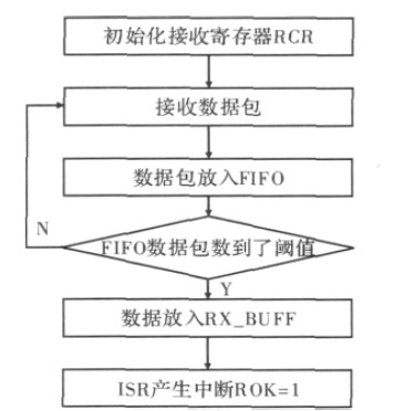
Figure 5 RTL8139 data receiving flow chart.
TCP / IP is a general term for a series of protocols. It is an indispensable part of Internet communication, including more than a dozen protocol standards. Here, it is necessary to read the readings of the household meters through the network, and the amount of data transmitted is small. And the real-time requirements are not high, do not need all the protocols, as long as the implementation of several necessary, under the trade-off, to achieve a balance between the minimum code, minimum resource requirements and functional implementation: only ICMP, TCP , IP, ARP 4 protocols, constitute a miniaturized TCP / IP protocol. Because any Ethernet data frame must be aware of the physical address of the other party when it is sent, this can be obtained through the ARP protocol, so the ARP protocol is implemented. The IP protocol is the transmission format of TCP and ICMP protocol data; the TCP protocol provides reliable and reconfigurable services; and the ICMP protocol is indispensable for debugging. In addition, when implementing the retransmission function, most of the practice is that the application layer does not participate. When retransmission is required, the data stored in the data buffer can be sent again by the TCP/IP protocol, but it is mainly processed by the single chip microcomputer. In the case of the device, since the resources of the microcontroller itself are limited, in order to reduce the use of the RAM, the frame data can be generated by the application layer when retransmission is required, which does not require much time. This also eliminates the need to store a frame of data in the buffer for retransmission, further saving RAM.
3 Experimental results and analysis
Connect the handheld RFID reader to the LAN switch through the network cable, and set the IP address of the reader to 192. 168. 1. 37, start the reader, switch and computer, and input ping192.168 in the command terminal of the computer. 1. 37 Command, the result is shown in Figure 6.
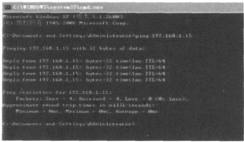
Figure 6 RFID connected to the LAN results.
As can be seen from Figure 6, the handheld RFID reader has been successfully connected to the LAN through the switch to establish a network connection with the computer.
After opening the RFID integrated management system in the computer and putting the experimental RFID card into the handheld RFID reader, the integrated management system reads the information as shown in Figure 7.
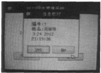
Figure 7 The integrated management system receives the information.
It can be seen from Fig. 7 that the handheld RFID reader successfully transmits the experimental card information read through the LAN switch to the integrated management system of the computer, realizing the function of the network interface.
4 Conclusion
The designed handheld RFID reader network interface hardware uses MSP430F149 as the control chip, using PM34 - 1 006M10 /100 /1 000M transformer as the isolation transformer, and fully supports the IEEE802. 3 standard highly integrated RTL8139 as the Ethernet controller chip. The whole system has the advantages of ultra-low power consumption, realizes the network function of RFID readers, and creates conditions for improving the competitiveness of products. At the same time, the network interface driver and TCP / IP C language development, with good readability and portability, can improve development efficiency and shorten the development cycle.
Copper-based PCB, it's the PCB that use copper as the base material and very commonly used in LED products and other electronics products since copper is the material have high heat dissipation.
PCB = printed circuit board and PCBA = printed circuit board assembly. For PCB, it means the copper circuits be printed on a board, and so the main composition of PCB are copper and board.
The copper is the circuits material and the circuits designed by the PCB designers. Depends on the current in the circuits, the PCB copper thickness could be done with 0.5oz-10oz. But the PCB designers need be noted that the copper track width/space need be enlarged with the thickness. For example, the minimum copper track width/space could be 3mil/3mil with 0.5oz, but would be 4mil/4mil with 1oz.
The PCB board could be rigid PCB, could be flex PCB and also could be Flex-Rigid PCB. And the materials could be FR4, PI, Aluminum, Copper-based, Rogers, Teflon, etc. They have different applications. For example, FR4 PCB is the most commonly used for rigid PCB and almost good for all electronics products; PI is the most commonly used for flex PCB; Aluminum and copper-based have good thermal diffusivity and always used for LED PCB ; Rogers PCB and Teflon PCB are always used for High Frequency PCB, etc.
We are the one-stop shop for all kinds of PCB manufacture service from PCB Prototype to big volume, which could save our customers a lot of time and money.
PCB Manufacture Capabilities
|
Features |
Capabilities |
|
Layers |
1-36 layers |
|
Material |
FR-4, Aluminum, Copper, Polyimide, high frequency (Rogers, PTEE, PI), etc. |
|
PCB Type |
FR-4 Standard PCB , Aluminum PCB , Copper-based PCB, HDI PCB , Rigid-Flex PCB, Flex PCB, Thick Copper PCB and Rogers PCB, etc. |
|
Board Thickness |
0.1mm-6.0mm |
|
Copper Thickness |
1/2oz-6oz(18um-210um) |
|
Biggest Board size |
600mm*1200mm |
|
Min Tracing/Spacing |
0.075mm/0.075mm (3mil/3mil) |
|
Min drilling Hole diameter |
0.15mm(6mil), 0.1mm(4mil)-laser drill |
|
Solder Mask |
Green, Black, White, Red, Yellow, Blue and Purple, etc. |
|
Silkscreen color |
White, Blue, Black, Red, Yellow |
|
Surface finish |
HASL Lead free, Immersion Gold (ENIG), Immersion Tin, Immersion Silver, OSP, Carbon oil, etc. |
|
Special Techniques |
Impedance Control, Gold Fingers, Blind/Buried vias, Peelable solder mask, Half holes, Via-in-Pad and Countersink hole, etc. |
PCB Products Show

PCB Factory Show

Copper-based PCB
Copper-based PCB,Heavy Copper PCB,Copper Core PCB,Extreme Copper PCB
ZhongFeng Electronic Technology Co., Limited , https://www.dopcba.com