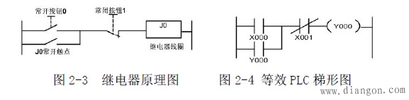
First, the jog circuit
1.1 Function introduction:
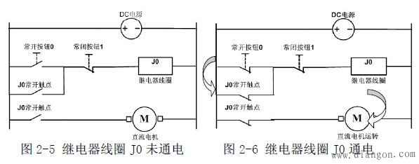
Second, the automatic holding circuit with stop
2.1 Function introduction
It is a basic form of maintaining the state of the circuit and is mainly used to maintain the state of the external signal.
2.2 Working principle
Turn on the power, press the normally open button 0, the relay coil J0 is energized, the J0 main contact is closed, and the motor is powered on. At the same time, the J0 auxiliary contact is self-locking and the motor continues to operate as shown in Figure 2-6. Stop and press the normally closed button 1. The relay coil J0 is de-energized, and the J0 auxiliary contact is disconnected. The motor is de-energized and stopped as shown in Figure 2-5.
2.3 Circuit Application
Below we compare the relay coil before and after power-on and power-on:
Third, self-retaining interlock circuit
3.1 Function introduction
One stop switch, two start switches, the signal that takes the first action first, the other signal is affected by the interlocking action, and does not act before the stop signal is not actuated.
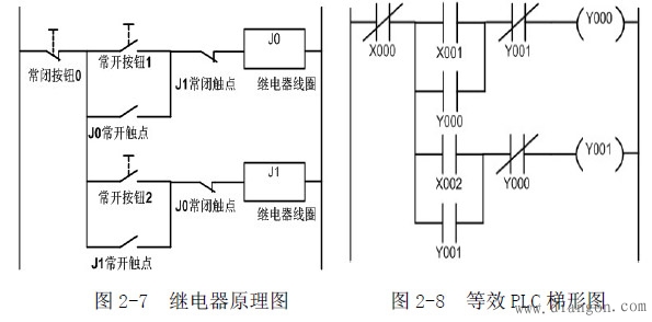
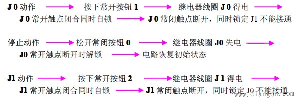
3.2 Working principle
3.3 Circuit Application
This circuit can be used for motor forward and reverse control.
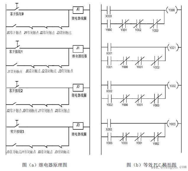
Fourth, the first action priority circuit
4.1 Function introduction
Among the lines of the plurality of input signals, the signal that is the first action takes precedence. When the first input signal is not removed, the other signals cannot be operated.
4.2 Working principle
Normally open button 0 to 3 No matter which one is pressed, its corresponding relay coil is energized, the corresponding normally open contact is closed and self-locking, and the J4 relay also acts to disconnect the other 3 groups of power supply, as long as the first power is available. The relay is not powered and the other relays will not operate.
4.3 Circuit Application
This circuit can be used as a responder as long as a reset switch is added to the power input.
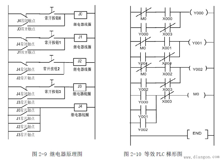
Fifth, the post action priority circuit
5.1 Function introduction
Among the lines of the plurality of input signals, the signal of the last action takes precedence. The state determined by the previous action is released by itself.
5.2 Working principle
When the normally open button 0 to 3 is pressed in any state where the circuit is energized, the corresponding relay coil is energized, its corresponding normally closed contact is opened, and the self-locking (self-holding) state of the other coils is released.
5.3 Circuit Application
This circuit can be added with a reset normally closed switch at the input end of the power supply for program selection, production period control circuit, and so on.
Sixth, time relay (also known as time delay relay)
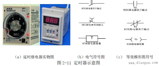
6.1 Function introduction
When the input action signal is added (or removed), the output circuit must pass the specified precise time to generate a jump change (or contact action). The time relay is divided into on-delay and disconnect according to function. Delay, instantaneous delay, etc.
The following focuses on the application of time-delayed relays.
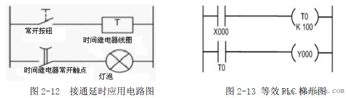
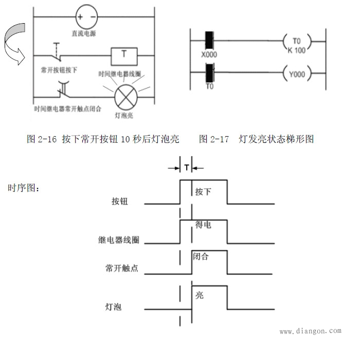
Figure 2-12 shows a simple delay-on application circuit. In order to facilitate the analysis principle, a light bulb is connected in series with the normally open contact of the time relay. Of course, you can also connect other loads in series, such as contactors, solid state relays, etc. Figure 2-13 shows the expression of the plc ladder diagram, schematic diagram and Figure 2 -12 is the same. In order to analyze the action flow, add power to the on-delay application circuit as shown in Figure 2-14, at which point the delay relay does not work.
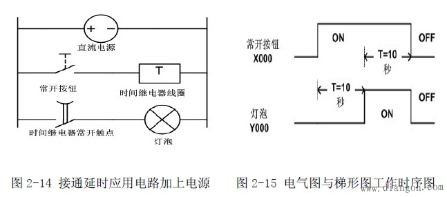
Assume that the preset time of the delay relay is 10 seconds. Press the normally open button, the time relay coil is energized and starts to count. After 10 seconds, the normally open contact is closed, and the bulb is energized. See Figure 2-16 until loose. When the normally open button is turned on, the time relay coil is de-energized, and the normally open contact returns to normal open. At this time, return to the state of Figure 2-14.
Seven, the counter 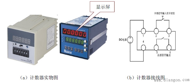
7.1 Function introduction
The device is driven by the transmission mechanism to indicate the device to be measured (addition count) or inverse count (subtract count), and when the number reaches the preset value, the output is turned on or off.
The following describes the addition counting application.
7.2 Wiring instructions
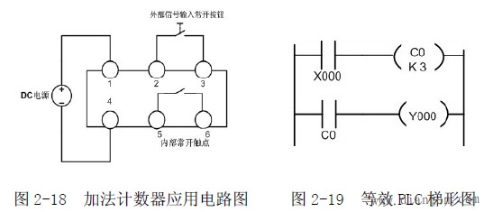
In Figure 2-18, pins 1 and 4 are power input terminals, pins 2 and 3 are signal input terminals, and pins 5 and 6 are internal normally open contact output terminals.
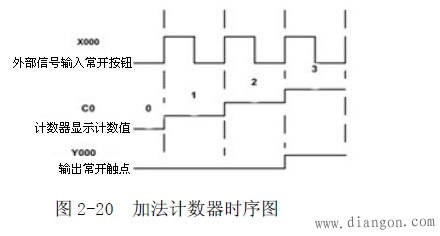
7.3 Working principle
Press and release the normally open button once, and the counter display window is incremented by one. It is assumed that the preset value of the counter is 3. When the value of the normally open button is pressed and released three times, the internal normally open contact is closed.
The PLC and relay related applications and principles provided above are for reference only and I hope to help you.
3.2V105Ah Lithium Ion Battery,105Ah 3.2V Phosphate Battery Cell,3.2V105Ah Deep Cycle Solar Battery,3.2V 105Ah Lifepo4 Forklift Battery
Jiangsu Zhitai New Energy Technology Co.,Ltd , https://www.jszhitaienergy.com