The ammeter and voltmeter are the two most basic and most important measuring instruments in the junior high school electrical experiment. The two watches are also the commonly used instruments in the middle school entrance examination. Some students lose points because they do not master their correct use methods, so they teach the students to master the ammeter and The use of voltmeters is very necessary. Let's talk about the few things that must be emphasized in the teaching of ammeters and voltmeters:
1, will look at the table
For example Figure 1
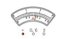
As shown, the dial is marked with the letter "A", which is an ammeter that measures the current intensity.
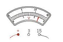
For example Figure 2
PDM-801A, PDM-801A-C, PDM-801A-F48
As shown, the dial is marked with the letter "V", which is a voltmeter for measuring voltage.
2, will receive the form
The ammeter must be connected in series in the circuit to be tested. The “+†pole of the ammeter must be extremely close to the “+†of the power supply. The “?†pole of the ammeter must be extremely close to the “?†of the power supply. The voltmeter must be connected in parallel to the circuit under test. At both ends, note that the positive and negative poles cannot be reversed. When using an ammeter, its two terminals must not be directly connected to the two poles of the power supply to avoid burning the ammeter due to excessive current.
3. The range of the selected table
There are three binding posts for the ammeter and the voltmeter. See how the wires are connected. For example, if the ammeter is connected to the two terminals “+†and “0.6â€, the range is 0.6 amps, and the number of the lower group on the dial is read; Table, if connected to the two posts "+" and "15", the range is 15 volts, then the upper set of numbers on the dial should be read. Before the experiment, if you do not know how to connect, you can first estimate the current intensity and voltage value of the circuit. If the estimated current intensity is less than 0.6 ampere, select 0 to 0.6 amp range. If the estimated current intensity is greater than 0.6 ampere, less than 3 amps, then select 0 to 3 ampere range. If it is not possible, use the test method. Fix one terminal and use the other end of the circuit to quickly touch the terminal of the maximum range. According to the test data, select the appropriate range. For the voltmeter, if the estimated voltage is less than 3 volts, the range of 0 to 3 volts is selected. If the estimated value is greater than 3 volts, then the range of 0 to 15 volts should be selected. It cannot be estimated that the test is also performed.
4, will test the circuit
After connecting the physical map according to the circuit diagram, the test circuit must be carried out, and the deflection of the pointers of the two tables must be carefully observed. If the pointer is not deflected, it means that the circuit is disconnected somewhere, and the positions of the two tables may be connected incorrectly. Deviation in the opposite direction indicates that the positive and negative terminals are reversed. If the direction of the pointer is too large, the range is selected too small. If the range is selected, it is not accurate enough. If the pointer is deflected, the direction is too small. The range is too large, and according to the actual situation of the test, the corresponding adjustment can be made, and then the experiment can be carried out.
5, will read the table
It is very important for the junior high school students. Some questions in the middle school entrance test give the two dials and the pointer position, so that the corresponding readings can be read out, and the physical quantities such as resistance, electric power, electric power, electric heat, etc. are calculated according to the reading. The first step is a mistake. Most of the latter questions are lost. First, figure out what each big grid is, and how much each small grid is. Each large grid represents 0.2 amps (Figure 1). Each small grid scale represents 0.02 amps. At this time, it can be accurate to 0.02 amps, and then look at the pointer position. The position indicated by the pointer is 1 large grid and 8 small grids, then the reading should be 0.36 amps.
In Figure 2, each large cell represents 5 volts, and each small cell is expressed as 0.5 volts. At this time, it can be accurate to 0.5 volts, and then look at the position of the pointer. The position of the pointer is 2 large cells and 4 small cells. , then the reading should be 12 volts.
6, will distinguish the similarities and differences between the two tables
Same point:
1 The positive poles of both meters are close to the positive pole of the power supply.
2 Both tables should pay attention to the measurement range.
difference:
1 The ammeter must be connected in series in the circuit to be tested, and the voltmeter must be connected in parallel at both ends of the circuit to be tested.
2 The ammeter cannot be directly connected to the two poles of the power supply. The voltmeter can be directly connected to the two poles of the power supply.
Current and voltage meter fault diagnosis method1. Tapping pressure method
When we use the instrument, we often encounter the phenomenon of good or bad operation of the instrument. Most of this phenomenon is caused by poor contact or virtual welding. For this case, tapping and hand pressing can be used.
The so-called "knocking" is to gently knock the board or part through a small rubber hammer or other tapping object to see if it will cause an error or a downtime. The so-called "hand pressure" is when the fault occurs, after the power is turned off, the inserted components and the plug and the seat are again pressed by hand, and then the power is turned on to try to eliminate the fault. If you find that the case is normal and the tap is not normal, it is best to re-insert all the connectors and try again. If you are not successful, you have to think about other methods.
2, observation method
Use vision, smell, and touch. In some cases, components damaged by the current voltmeter will change color, blister or burnt spots; burnt devices will produce some special odor; short-circuited chips will be hot; visible soldering or visible to the naked eye Desoldering.
3. Exclusion method
The so-called elimination method is a method for judging the cause of the failure by plugging and unplugging some boards and devices in the current voltmeter. When the instrument returns to normal after removing a board or device, the fault has occurred there.
4, replacement method
Two current and current voltmeters of the same type are required or there are enough spare parts. Replace a good spare with the same component on the faulty machine to see if the fault is eliminated.
5, comparison method
Two current and voltage voltmeters of the same type are required, and one is operating normally. Use this method to have the necessary equipment, such as a multimeter, oscilloscope, etc. According to the nature of the comparison, voltage comparison, waveform comparison, static impedance comparison, output comparison, current comparison, etc.
The specific method is: let the faulty meter and the normal meter run under the same conditions, and then detect the signals of some points and then compare the two groups of signals measured. If there are differences, it can be concluded that the fault is here. This method requires the maintenance personnel to have considerable knowledge and skills.

6, lifting temperature method
Sometimes, the current voltmeter works for a long time, or when the working temperature in summer is high, the fault will occur. The shutdown check is normal. After stopping for a while, the power is turned on again and normal. After a while, the fault occurs again. This phenomenon is caused by the poor performance of individual ICs or components, and the high-temperature characteristic parameters fail to meet the requirements of the index. In order to find out the cause of the malfunction, the temperature rise and fall method can be employed
The so-called cooling, that is, when the fault occurs, use cotton fiber to wipe the anhydrous alcohol in the part that may be faulty, to cool it, and observe whether the fault is eliminated. The so-called heating is artificially raising the ambient temperature, such as using a soldering iron to close the suspected part (be careful not to raise the temperature too high to damage the normal device) to see if the fault occurs.
7, riding the shoulder method
The shoulder riding method is also called parallel method. Place a good IC chip on the chip to be inspected, or connect good components (resistance capacitors, diodes, transistors, etc.) in parallel with the components to be inspected, and keep in good contact. If the fault is caused by an open circuit inside the device or This method can be used to eliminate the cause of poor contact.
8, capacitor bypass method
When a circuit of the current voltmeter produces a strange phenomenon, such as a display disorder, the capacitor bypass method can be used to determine the portion of the circuit that is likely to fail. Connect the capacitor across the power supply and ground of the IC; connect the transistor circuit across the base input or collector output to observe the effect on the fault. If the capacitor bypass input is inactive and the fault disappears when bypassing its output, it is determined that the fault is present in this stage of the circuit.
9, state adjustment method
Generally speaking, do not touch the components in the current and voltage meter circuit before the fault is determined, especially the adjustable device, such as the potentiometer. However, if a reference is taken in advance (for example, position mark or measured voltage value or resistance value before untouched), it is allowed to be touched if necessary. Maybe after the change, sometimes the fault will be eliminated.
10. Isolation method
Fault isolation does not require the same type of current voltmeter or spare parts for comparison, and is safe and reliable. According to the fault detection flow chart, the segmentation and encirclement gradually narrows the fault search range, and then cooperates with the signal comparison and component exchange methods, and generally finds the fault location.
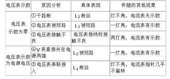
(1) When using a voltmeter to measure the voltage across a certain circuit, if the voltmeter has a number, it means that the voltmeter is connected to the two poles of the power supply. If there is an open circuit in the circuit, the disconnection point is The circuit part in which the voltmeter is connected in parallel.
(2) If there is no indication in the voltmeter, there is no current flowing through the voltmeter. The possible reason is that the terminal of the voltmeter is in poor contact; the circuit under test is short-circuited; the part other than the circuit under test has an open circuit.
(3) The ammeter pointer is almost unmoved, that is, the ammeter is not shown. The cause of the fault may be an open circuit from the two terminals of the ammeter to the circuit between the two poles of the power supply, or a short circuit of the ammeter.
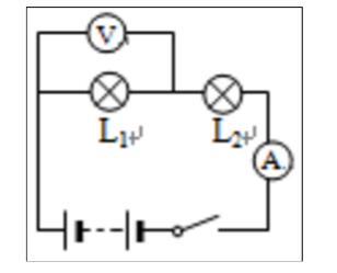
(4) The lamp does not emit light. The cause of the fault may be that the filament is blown, or the lamp is short-circuited, or an open circuit occurs somewhere in the circuit between the lamp post and the two poles of the power supply. Taking the circuit diagram shown in the following figure as an example, starting from the display of the voltmeter, the failure analysis table shown below can be obtained.
Description:
(1) Since the voltmeter and the lamp L1 are connected in parallel, the branch where L1 is located is not on the dry road.
(2) When the voltmeter is connected in series to the circuit, because the resistance of the voltmeter is far greater than the resistance of the bulb, according to the partial pressure of the series circuit, the voltage at the ends of the voltmeter will also be much larger than the voltage of the bulb, which is generally considered to be equal to voltage.
(3) The above table does not consider the case where the voltmeter and ammeter are broken. It can be seen from the table that different faults have different phenomena, so we can judge the inherent fault according to the external phenomenon. When using the above table to solve problems, it is important to understand the causal relationship between causes and phenomena rather than memorizing.
1. Care should be taken when handling and disassembling the meter. It should be handled gently and not subject to strong vibration or impact to prevent damage to the parts of the meter, especially the bearings and hairspring of the meter.
2. When installing and disassembling the meter, the power should be cut off to avoid personal accidents or damage to the measuring mechanism.
3. Before the meter is connected to the circuit, first estimate whether the current, voltage, etc. to be measured on the circuit are within the maximum range of the meter, so as to avoid overloading the meter and damaging the meter. When selecting the maximum range of the meter, it is better to measure 1.5~2 times.
4. When measuring current, the ammeter should be connected in series with the circuit under test; when measuring voltage, the voltmeter should be connected in parallel with the circuit under test. When measuring DC current or DC voltage, pay special attention to the “+†terminal of the meter and the “+†pole of the power supply. The “one†terminal of the meter is connected to the “one†pole of the power supply. There is no need to pay attention to polarity when measuring AC current or AC voltage.
5, the lead of the meter must be appropriate, to be able to bear the load when measuring without overheating, and does not cause a large voltage drop and affect the meter reading. If the meter has a dedicated wire, it should be connected to a dedicated wire when in use. The connected parts should be clean and secure so as to avoid contact failure and affect the measurement results.
6. The pointer of the meter must always pay attention to the zero adjustment. Usually the pointer should be at the zero position. If there is a slight gap, adjust the zero calibration screw on the meter to return the pointer to the zero position.
7. The meter should be wiped regularly with a dry soft cloth to keep it clean.
950W Human Sensor PTC Fan Heater
950W Human Sensor Ptc Room Heater,Ptc Fan Heater,Ptc Tower Heater,Ptc Electric Fan Heater
Foshan Shunde Josintech Electrical Appliance Technology Co.,Ltd , https://www.josintech.com