1. Introduction to planar low-pass filter
With the increasing frequency and miniaturization of microwave links, it is becoming more and more common to integrate low-pass directly in the link. At the same time, many chip-based low-pass are mostly micro-band filters implemented on high dielectric ceramic sheets. Ceramic chip type chip capacitors, inductors, and equalizers all require a planar low-pass design concept.
The model and structure of the common low-pass filter in ADS is shown in Figure 1.
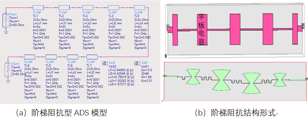
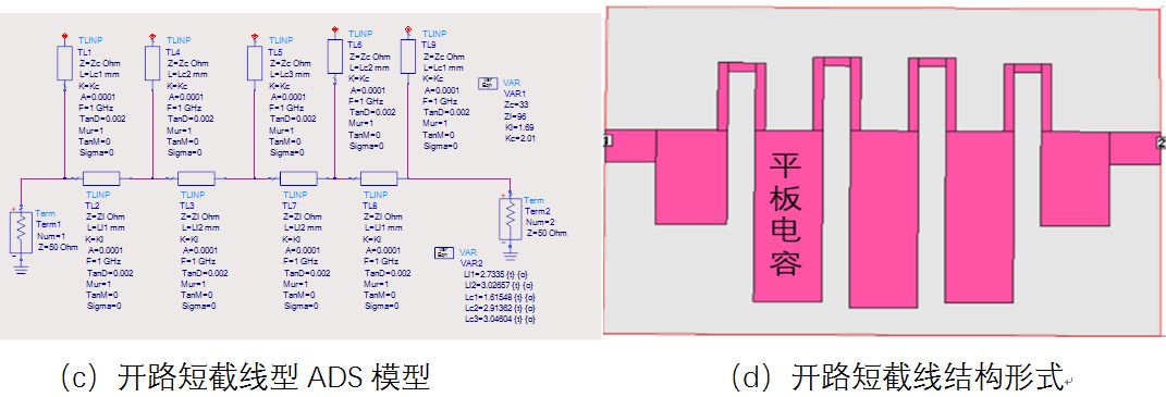
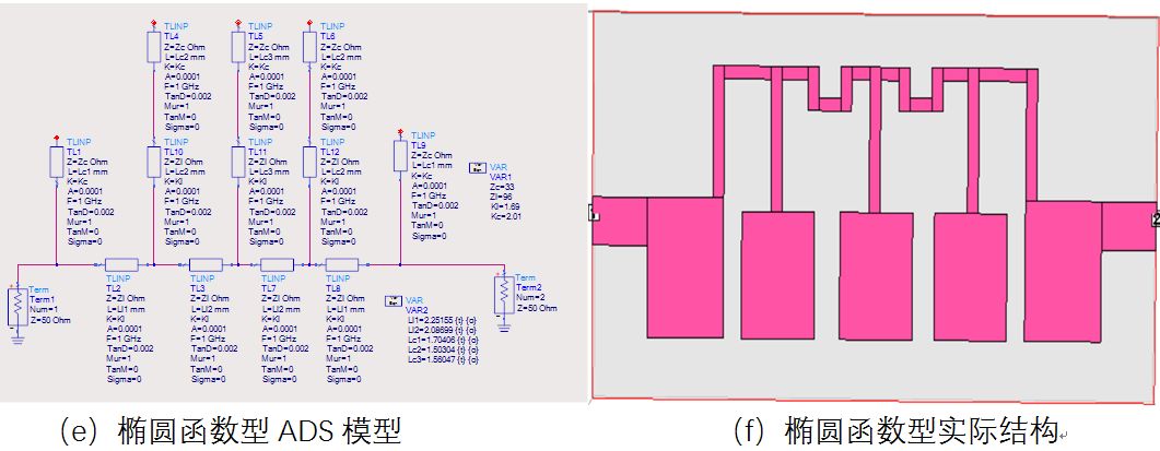
Figure 1 Common planar structure low-pass filter
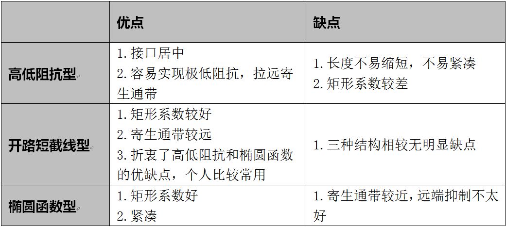
The advantages and disadvantages of the three structures are shown in Table 1. In general, the design of the higher requirements can be combined with the advantages and disadvantages of the three structures.
Table 1 Comparison of the advantages and disadvantages of the three structures
2. Theoretical basis of planar low-pass filter design
The theoretical basis of this summary is derived from Chapter 4/5 of Microstrip Filters for RF and Microwave Applications 2001. The core theory is the high-low impedance line equivalent circuit of Figure 2. The conclusion is that a high-impedance line can be equivalent to an inductor, and a low-impedance line is equivalent to a capacitance to ground. (If you understand that the characteristic impedance of the transmission line is expressed as sqrt(L/C) in the differential form, the high resistance L must be large, and the low resistance C must be large, you can understand the equivalent principle.)
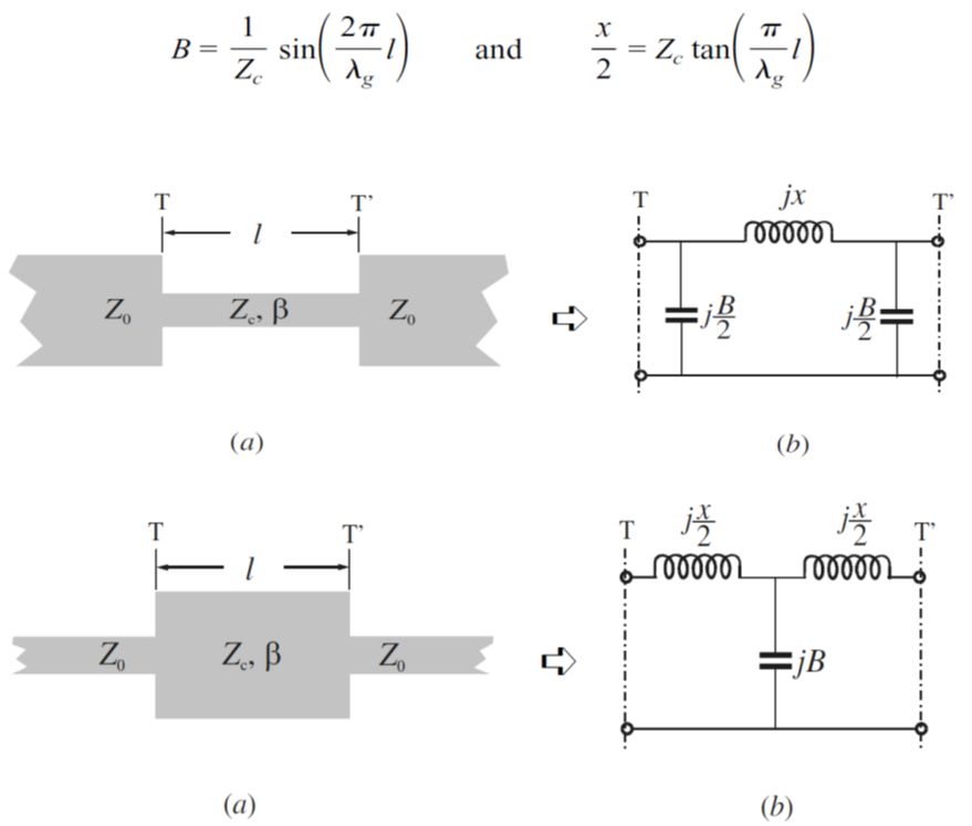
Figure 2 High and low impedance line equivalent circuit
3. Plane low-pass design
A planar low pass follows the following design steps.
1) Plan high and low impedance line impedance. High resistance is limited by line processing capability and power capacity. Generally, low power applications can be taken up to 0.15mm. The low resistance width is limited by the filter size and is limited by the aspect ratio. (The higher the ratio of high and low impedance, the farther the parasitic passband is, but the parasitic passband means that the near-end suppression will be poor, so the impedance of each branch can be flexibly configured during design to achieve the balance of parasitic passband and rectangular coefficient)
2) ADS modeling and simulation to obtain initial electromagnetic simulation parameters
3) Electromagnetic simulation verification optimization
This example uses a 10 GHz planar low pass as an example for the convenience of a hybrid structure.
1) Planning high and low impedance lines
High and low impedance planning is to compromise the number of stages / size and electrical performance, there is an iterative process in the actual design. There are many tools for high and low impedance calculations. Here is a recommended one: polar SI9000 (which can be searched by Baidu), which is a very practical tool for calculating the characteristic parameters of transmission lines. In this example, the processing limit of high resistance is 0.15mm, and the size of the low-resistance and the parasitic passband are 1mm wide. The characteristic parameters (characteristic impedance and effective dielectric constant) of 1mm line width can be obtained by calculation in Figure 3: W=1mm Z =33 ohm Er=(2.98/2.16)^2=1.90 (the speed of light is proportional to the square of the phase velocity) W=0.15mm Z=96 ohm Er=1.69
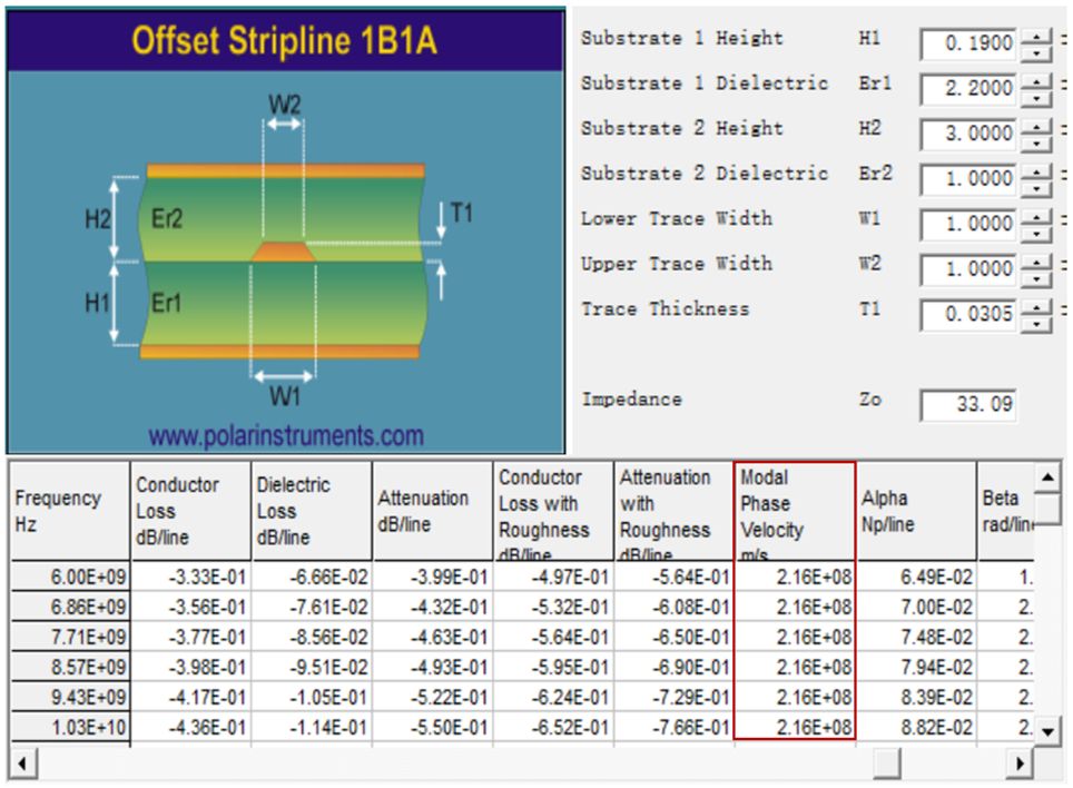
Figure 3 Transmission line impedance calculation
2) ADS modeling
In ADS, an ideal circuit model is established by cascading high and low impedance transmission lines to obtain the initial parameters of electromagnetic simulation. Personally, TlineP in Tline-ideal in ADS is used. The model has three parameters: impedance/effective dielectric constant/length, front. Two parameters have been obtained in the high and low impedance line planning. The model is modeled with only one variable of physical length. The 1/8 wavelength can be used as the initial value, and then the accurate physical length can be quickly obtained by optimization in ADS. The detailed model is shown in Figure 4.
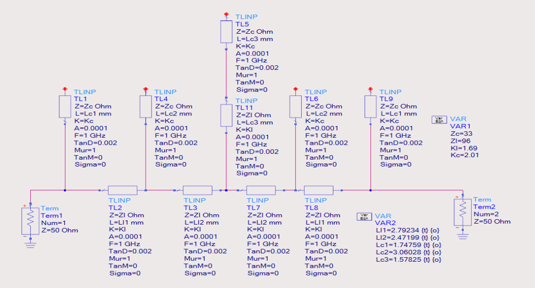
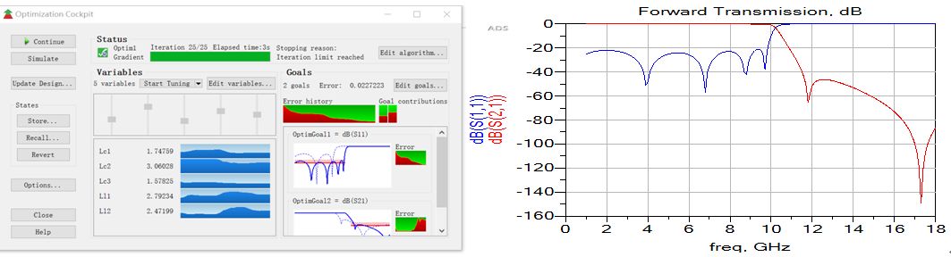
Figure 4 ADS model optimization to obtain electromagnetic simulation dimensions
3) Sonnet electromagnetic simulation
All planar structure microwave devices are used to simulate using sonnet. Sonnet can change the structure shape at will, which is very close to the method used in actual debugging, and the simulation speed is very fast, which is very suitable for electromagnetic simulation of planar structures.
The initial electromagnetic simulation model based on the dimensions obtained in the ADS simulation in sonnet is shown in Fig. 5.
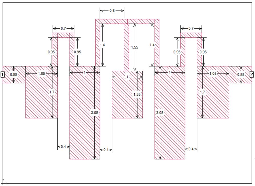
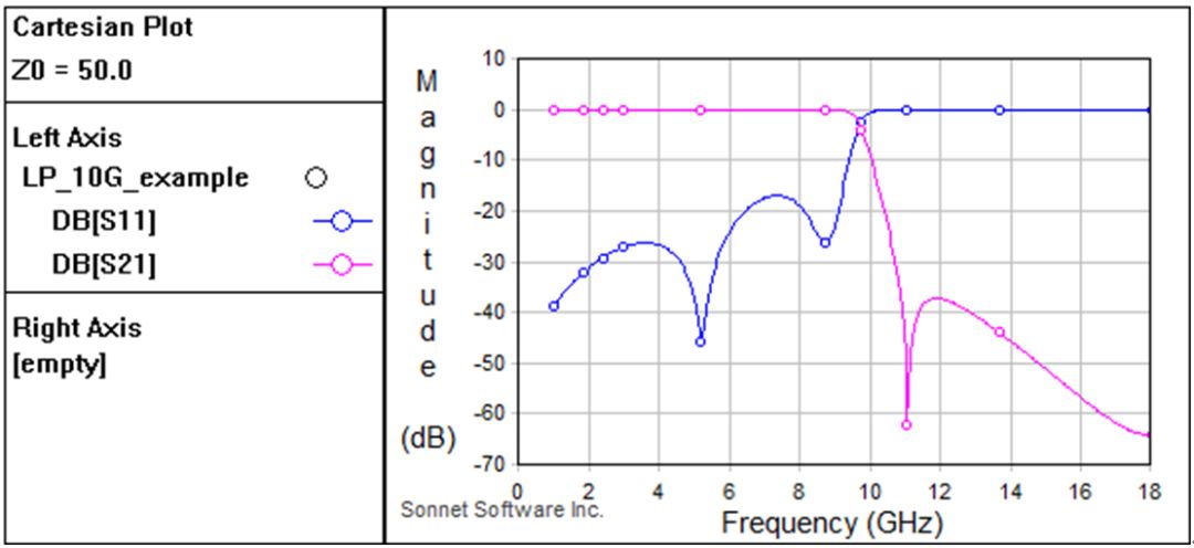
Figure 5 Sonnet's first electromagnetic simulation structure and results
Through electromagnetic simulation, it can be found that the parameters given in the ADS model are very accurate, and there is basically no need for optimization in electromagnetic simulation.
However, the model in ADS can not simulate the coupling effect between the various stubs, and the discontinuity effect of the joint. According to experience, it is usually only necessary to fine-tune the length of the high-resistance line to get a good design result.
Lithium Battery Pack For Hybrid Electric Locomotive
Lithium Battery For Electric Car,Cylindrical Battery,2000-2500Kw Lifepo4 Battery System,Ce Certificated Lithium Battery
Henan Xintaihang Power Source Co.,Ltd , https://www.taihangbattery.com