One of the biggest advantages of LED technology is that it can produce pure color light with extremely narrow spectrum in the form of electromagnetic radiation, and it has high efficiency and no heat radiation. If the color produced is exactly the color you want, it's great, but in general lighting applications, what we really want is "white" light. In other words, we need to mix multiple colors in precise proportions, similar to the spectrum of sunlight that reaches the human eye after filtering through the Earth's atmosphere.
Although similar to fluorescent lamps, it is possible to obtain white light from an LED source by applying a layer of phosphorous material on top of the blue or ultraviolet illuminator, but the composition of the actual phosphorous material and its thickness and coating position remain all major LEDs. The issue is widely discussed by manufacturers, and this is reflected in the fact that manufacturers announce newer and more efficient research results every month. Moreover, the quality of the generated light is also constantly increasing, and the perceived quality of the human eye is actually measured by measuring the correlated color temperature, that is, the black body temperature (CCT) which is very close to the perceived color of the lamp. This is a very important issue because the light produced by early fluorescent lamps is a bit dazzling, which has led to the “cold encounter†of early compact fluorescent lamps.
Another way to get white light from an LED is to accurately mix red, green, and blue light (RGB) from a three-color illuminator at the correct ratio so that not only white light but also the associated color temperature can be obtained. Figure 1 shows a simple application circuit that uses an 8-bit microcontroller in an eight-pin package to control the tri-color LED. The relative brightness of the three illuminators is controlled by simple software technology. Each illuminator can achieve 6-bit resolution (providing sixty-four brightness levels), which is sufficient for precise control of color output (white light) and selection of required CCT .
The PIC12HV615 flash microcontroller in the figure integrates a shunt regulator, an oscillator that provides an 8MHz clock, a reset circuit, and an analog-to-digital converter to provide a complete and flexible single-chip solution. The in-circuit programmable functionality of this flash component also allows the color calibration process to be performed at production time, providing a way to compensate for differences in performance and differences between components of various illuminators.
Long LED life is prone to chroma shift
The solution in Figure 1 has many applications, such as in automotive dashboard illumination where the color output of each module is required to match the color of the adjacent module. More and more applications called situational lighting have emerged, and of course, there are some obvious flaws.
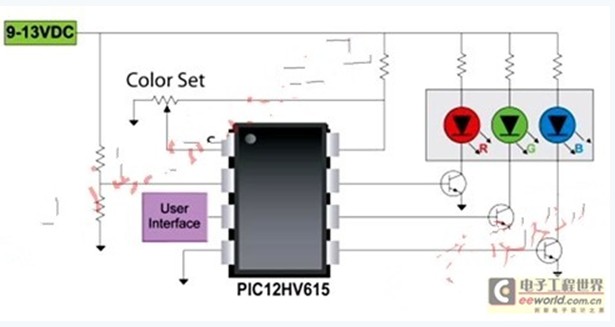
Figure 1 Example of a simple white LED system
First, this solution is less efficient because it is a linear solution and the current limiting resistors in series with each illuminator consume some power. There will be more problems throughout the lifecycle of the application.
In fact, one of the main advantages of LED technology is the extremely long working life, but this also leads to the problem of chromatic drift. After working for 50,000 hours or more, the LED's light output will gradually drop to 70% of its nominal value. Compared to incandescent bulbs, which are suddenly scrapped after 1,500 hours of use, their service life is indeed very long. But unfortunately, the CCT of white LEDs changes during these 50,000 hours, and heats up as the phosphor ages, approaching blue. Even RGB LED solutions have similar problems, and as the three-color illuminator slowly ages at different speeds at different speeds, CCT chromatic drift will still occur.
By using the intelligent capabilities of the microcontroller, a variety of techniques can be devised to compensate for component aging by using predictive algorithms or by implementing an infinite loop control system. Many manufacturers use light-sensitive components that can solve the chroma drift problem once when used with a simple PID algorithm, which of course increases the cost of the solution. Because changes are extremely slow in thousands of hours, high computational performance is not required, and even the lowest cost 8-bit microcontroller can be used to implement this control mechanism. This mechanism not only compensates for the aging of the LED, but also compensates for the aging of the drive circuit. This advantage is very important for such a long application life time.
Temperature management challenges lighting applications
Another challenge for general lighting applications is temperature management. As described above, high-power LEDs do not consume excess energy when generating electromagnetic radiation in a narrow spectral range (in the visible spectrum), but still generate heat. The difference with a light source such as an incandescent bulb is that this heat can only be transmitted by direct contact (conduction) rather than radiation. In order to be compatible with incandescent bulb lighting systems, important limitations are imposed on the design of general lighting systems such as ancillary equipment. In other words, lighting systems designed for incandescent bulbs of a given power rating are difficult to accommodate for LED lamps of the same power because the heat transfer path can be very limited. A high thermal resistance path can cause the LED illuminator to overheat quickly, destroying the phosphorous material (for white LEDs) and quickly damaging the LED junction.
Power conversion / control for LED focus
All of the focus of the LED is focused on achieving maximum luminous efficiency (lm/W), so the efficiency of the drive/control circuit must be equally valued. The LED is a relatively low voltage component (Vf ~ 3-4 volts), which does not match the high voltage 110 ~ 220 volts provided by the mains. In addition, in order to operate at the optimum efficiency level and maintain a constant light output, precise control of the LED current is required. Only switching power supplies can provide the high efficiency required for this conversion.
Using multiple constant current drive topologies to perform the required power conversion, isolation, power factor correction, and/or improvement to existing solutions may require two levels of processing. The input voltage is first reduced to the intermediate voltage, where conventional techniques are used to meet power factor correction (PFC) and high voltage isolation requirements, while the second stage is responsible for meeting LED current and temperature control requirements. Figure 2 shows a smart LED solution that uses the boost converter MCP1630 in a constant current configuration. A small 8-bit microcontroller provides a flexible clock source, programmable current set point (for the drive circuit to meet different LED module specifications) for further power-saving dimming, and remote temperature sensor Dead loop temperature control (integrated temperature sensor such as MCP9700 or thermistor).

Figure 2 Schematic diagram of the smart LED solution
Like many switching power controllers, the MCP1630 provides overtemperature detection. However, due to the large difference between the temperature of the driver circuit and the temperature of the actual LED module, the over-temperature detection function and the dead-loop temperature control function of the MCP1630 can complement each other. A microcontroller-based intelligent solution provides great flexibility, and the power output to the LED module gradually decreases as its temperature approaches a critical threshold until equilibrium is reached, rather than abruptly shutting down the system or only issuing an alarm. This feature is very important for component manufacturers, especially where the LED lamp is designed and operated independently of the lighting system and does not guarantee proper system temperature design.
Perhaps the biggest advantage of using an intelligent drive design, that is, using a small microcontroller to monitor the LED driver circuit is to make the solution more intelligent and functional with just a few lines of code. A simple digital protocol, such as DMX-512 or DALI, is implemented using the serial communication interface built into the microcontroller, making the communication interface easy to implement. Ethernet networks can be used for more advanced system integration or wireless communication using the ZigBee protocol.
Moreover, after connecting each lighting point, a new energy management system can be designed to further improve the efficiency of the entire home or office building system through a more holistic approach through energy saving strategies.
Under normal circumstances, if new solid-state lighting, especially power LED solutions, have an impact on general lighting and realize their potential, it is best to be an intelligent solution--using small-sized wisdom realized by a low-cost microcontroller, and then join After the lighting scheme, many obstacles hindering the introduction of prior art can be removed. Smart solutions help calibrate color, dim, manage heat and communication, making solid-state lighting a cost-effective alternative to energy efficiency in today's general lighting.
Edit: Nizi
We are manufacturer of 3M type wire connectors, UY connector, UY2 connector, UR connector, UB connector, UG connector and UDW2 connector are all available on sales. This wire connectors are used to connect two wires safely and fast with gel filling inside.
We want to tell you that we have made out a new product-AMP Picabond Connector.It is our hot product now.We can also sell you the tools for all wire connector.

Wire Splice Connectors, Inline Splice Connectors, Telephone Wire Connectors, Wire To Wire Connectors, Wire Crimp Connectors
NINGBO YULIANG TELECOM MUNICATIONS EQUIPMENT CO.,LTD. , https://www.yltelecom.com