On the physical line, due to noise interference, signal attenuation and other reasons, errors often occur during data transmission, and the physical layer is only responsible for the transparent transmission of the structure's original bit stream, making it impossible to perform any error control. Therefore, when data needs to be transmitted on one line, in addition to having a physical line (link), there must also be some necessary procedures to control the transmission of these data. Adding the hardware and software implementing these procedures to the link constitutes the Data Link Layer.
What is the CAN busCAN stands for "Controller Area Network," or "Controller Area Network," an ISO-standard serial communication protocol. The CAN bus was developed and designed by Germany's BOSCH company to meet the needs of the increasingly large electronic control system in automobiles. Its greatest feature is its good scalability, high-speed communication that can withstand large amounts of data, and it is highly stable. The ISO organization standardized the CAN bus through ISO11898 and ISO11519, which made it possible to establish the status of the European automotive bus standard as early as possible. Today, CAN bus has been highly recognized by the industry, and its application has also extended from automotive electronics to industrial automation, marine, medical equipment, industrial equipment and other fields.
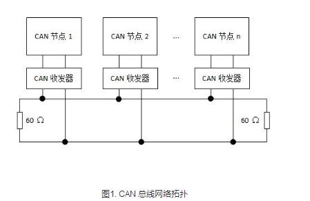
CAN bus network topologyThe physical connection of the CAN bus requires only two wires, often referred to as CAN_H and CAN_L, for data transmission via differential signals. The CAN bus has two levels, a recessive level and a dominant level. These two levels have an AND relationship similar to the drain I/O level signal:
If the recessive level meets, the bus appears as a recessive level;
If the dominant level meets, the bus appears as a dominant level;
If the recessive level and the dominant level meet, the bus appears as a dominant level.
A typical CAN bus network topology is shown in Figure 1. Note that termination resistors at both ends are required.
1, the communication mechanism
2, data frame
3, error detection
4, the frame format
5, bit timing and synchronization
CAN bus frame formatData is sent out in bits in this format. There are a total of 5 different types of frames on the bus.
The CAN bus protocol specifies five types of frames, which are data frames, remote control frames, error frames, overload frames, and frame intervals. In practice, data frames are used most frequently. The use of various frames is shown in Table 1.
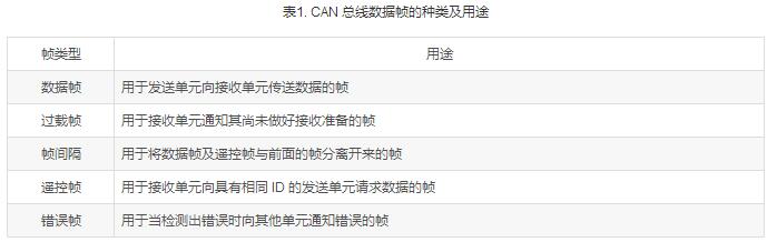
The data frame is used to send and receive data between nodes, which is the most used frame type; the remote frame is used to receive data from the receiving node to the sending node; the error frame is used to notify other nodes when a certain node finds a frame error; the overloaded frame is The frame used by the receiving node to inform the sending node of its own receiving capability; the frame used to separate the data frame and the remote frame from the previous frame.
The data frame is divided into a standard frame (2.0A) and an extended frame (2.0B) according to the length of the arbitration segment.
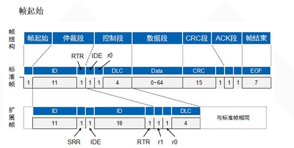
The frame start consists of a dominant bit (low level), the sending node sends the start of the frame, and the other nodes are synchronized to the start of the frame;
The end of the frame consists of 7 invisible bits (high level).
Arbitration segment
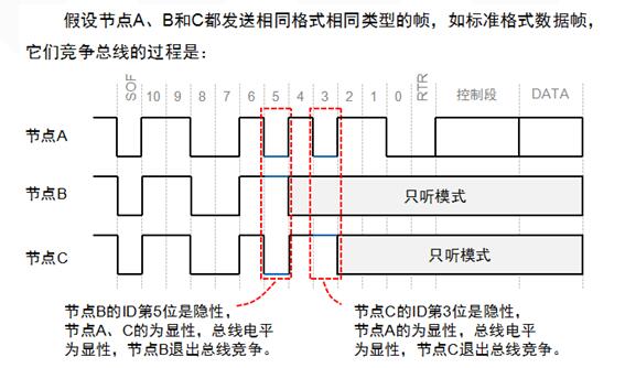
How can the CAN bus solve the problem of multi-point competition?
The answer is given by the arbitration section.
The CAN bus controller monitors the bus level while sending data. If the level is different, it stops sending and performs other processing. If this bit is in the arbitration segment, bus contention is exited; if it is in another segment, an error event is generated.
The smaller the frame ID, the higher the priority. Since the RTR bit of the data frame is a dominant level and the remote frame is a recessive level, the data frame takes precedence over the remote frame when the frame format and the frame ID are the same, and the IDE bit of the standard frame is a dominant level. The IDE frame of the extended frame is a stealth level. For standard frames and extended frames with the same first 11-bit ID, the standard frame has a higher priority than the extended frame.
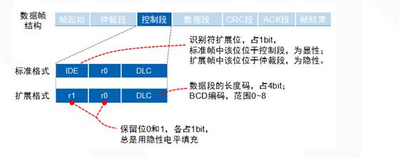
Control section
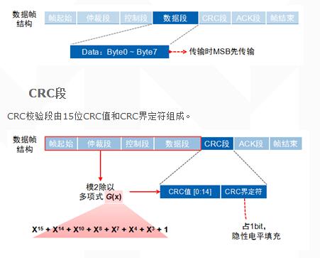
Data segment
0-8 bytes, short frame structure, real-time performance, suitable for automotive and industrial control;
A total of six bits, the control segment of the standard frame is composed of the extended frame flag bit IDE, reserved bit r0, and data length code DLC; the extended frame control segment is composed of IDE, r1, r0, and DLC.
ACK segment
When the receiving node receives no frame error from the start of the frame to the CRC segment, it will send a dominant level in the ACK segment, and the sending node will send a recessive level. The line and result are dominant levels.
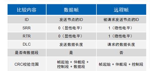
Remote frame
The remote frame is divided into 6 segments, which are also divided into standard frame and extended frame, and the RTR bit is 1 (recessive level)
CAN is a highly reliable bus, but it also has five errors.
CRC error: This error occurs when the transmitted and received CRC values ​​are different.
Format error: This error occurs when the frame format is illegal;
Response error: The sending node did not receive a response message during the ACK phase and this error occurred.
Bit sending error: When the sending node finds that the bus level does not match the sending level when sending the message, this error occurs.
Bit stuffing error: This error occurs when the communication rule is violated on the communication cable.
When one of these five errors occurs, the sending or receiving node will send an error frame
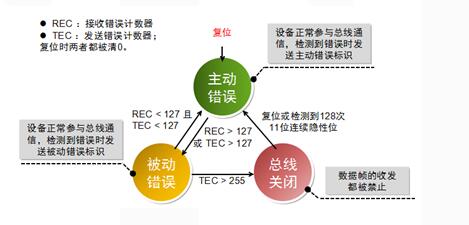
In order to prevent certain nodes from making mistakes, they always send error frames and interfere with the communication of other nodes. The CAN protocol specifies the three states and behaviors of nodes.
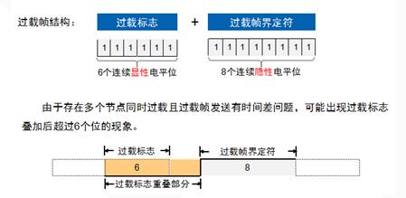
Overload frame
When a node is not ready to receive, an overload frame is sent to notify the sending node.
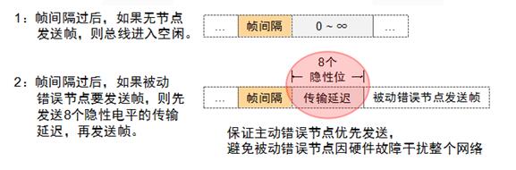
Frame interval
Used to isolate data frames, remote frames, and frames in front of them. Error frames and overload frames are not preceded by frame intervals.
Motorcycle Radio,High Quality Motorcycle Radio,Motorcycle Radio Details, CN
Jiangmen soundrace electronics and technology co.,ltd. , https://www.soundracegroup.com