introduction
This article refers to the address: http://
For many years, consumers have become accustomed to relying on the convenience and enhanced security provided by passive car alarm systems. This system consists of a key fob carried by the driver and a base station installed in the car. The two work together to determine if the driver has the right to start the car; more importantly, the system can prevent illegal users from using the car. Although the functionality of the car alarm is simple, the basic implementation technology is very complicated and interesting. This article explores the hardware and software issues of car alarms and gives a noteworthy review of design and safety considerations.
Communication
Currently in passive car alarm systems, the primary communication method between the key fob and the car is to utilize a modulated magnetic field generated by the car's anti-theft base station from low frequency (typically 125 kHz) alternating current. The main purpose of the magnetic field is three: A) the energy source of the key fob, so it is called "passive"; B) the carrier that transmits information from the base station to the key fob (ie "downlink"); C) Carrier that transmits information from the key fob to the base station (ie "uplink").
Since car anti-theft systems require complete passive (eg, no battery) operation, the magnetic field characteristics of the key fob are particularly suitable for this application. Both "downlink" field detection and "uplink" field modulation can be implemented with circuitry that consumes very little power. In addition, it is easier to use the field energy of the saturated magnetic field to power these circuits in the key fob.
During the system design phase, some key parameters must be carefully considered, such as the energy requirements of the key fob (which affects the geometry and drive level of the antenna coil), and the security of the verification process (which has a direct impact on response time). . This will be explained in detail below.
System interface
The system architecture of a car alarm is divided into several extraction layers, each of which represents a different system interface. Figure 1 shows a visual representation of these layers.
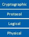
Figure 1 car alarm interface layering
Physical layer
The bottom layer of the car alarm system is the physical layer, which contains an antenna coil mounted on the car, which can generate enough magnetic field to detect and modulate the antenna coil installed in the user's key card.
Magnetic field generation and modulation
Depending on how the magnetic field supports data transmission, car alarm systems can be divided into two categories: half-duplex and full-duplex. In a half-duplex system, the on-board antenna coils are alternated between energy transfer and data transfer cycles, while data modulation uses frequency shift keying (FSK). An illustration of this communication method is shown in Figure 2. Two points can be clearly seen from Fig. 2: First, due to the need to repeatedly perform energy transmission, such as charging the key card, the data transmission rate is greatly reduced; second, the modulated signal is extremely small compared to the magnetic field during energy transmission. Therefore, it is more susceptible to interference from ambient noise, resulting in a reduction in transmission distance. These characteristics make the half-duplex system gradually weaker.
Currently mainly used is a full duplex system. In this system, the vehicle antenna coil performs energy transfer and data transmission simultaneously, while the data modulation uses amplitude shift keying (ASK). Figure 3 shows an illustration of this communication method. Obviously, this method has a much higher data transfer rate than a half-duplex system due to the ability to synchronize data transfer and key card power or charging. Moreover, a constant carrier field can often mask out interference and ensure robust and reliable communication during data transmission. In addition, this scheme can be implemented using a simple envelope detection circuit. In view of the current popularity of full-duplex car anti-theft systems on the market, such systems will be specifically discussed below.
System interface: logical layer
Above the physical layer is the logical layer. This layer relates to the characteristics and requirements of data transmission and encoding on a magnetic field. It applies to everything from cars to key fobs (often referred to as "downlinks") and from key fobs to cars (called "uplinks").
Downlink
The downlink information is encoded using a pulse length modulation method, typically binary pulse length modulation (BPLM) or Quad Pulse Length Modulation (QPLM). This method is based on inserting a fixed length carrier field time slot "Tgap" and setting the time slot to time slot time interval to a predetermined number of times: T0 corresponds to a logical "0" and T1 corresponds to a logic "1". The advantage of this scheme is that it embeds the energy transfer from the car to the key fob into the data encoding and ensures that the fob has enough power to process the encoded data. However, this coding method also has a disadvantage in that the data transmission baud rate must depend on the logical value of the data bit stream being transmitted because the transmission time of each binary state is different. A more detailed illustration of this encoding method is given in Figure 4.
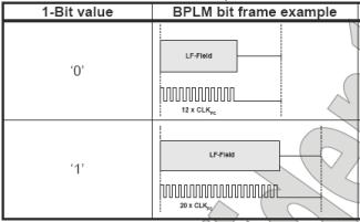
Figure 4 BPLM coding method
QPLM is a variant of BPLM. With this modulation method, two bits are transmitted after one time slot, so that more energy is available at the transceiver end. In addition, its average baud rate is higher than BPLM. This coding method is identical to the basic implementation principle of BPLM, except that the number of allowed states is extended from 2 to 4, and the predetermined slot interval is extended to cover more states. Figure 5 shows a visual representation of QPLM.
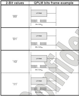
Figure 5 QPLM coding method
Uplink
Information communication from the user key card to the in-vehicle base station is generally Manchester or Bi-phase encoding. These encoding methods share some characteristics different from the downlink: A) the average duty cycle of the encoded bit stream is always 50%; B) the time to transmit the encoded data depends only on the baud rate. Both of the above encoding techniques are capable of extracting the clock from the encoded data stream because all time periods in the encoded bit stream are quantized to T or 2T (T represents "half bit"). The data rate is fixed at 1/(2T). The clock extraction only needs to detect the minimum time period factor T and synchronize its phase with the encoded bit stream.
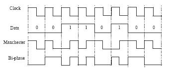
Figure 6 Manchester and Bi-phase coding
Protocol layer
The protocol layer defines a grouping of individual data bits to enable communication between the in-vehicle base station and the key fob. It defines how many bits are there and in what order they are transferred between the reader and the transceiver. To make a simple analogy, this is similar to the grammatical rules of using words to form sentences. The protocol layer is like a sentence made up of logical layers, and the logical layer is equivalent to words. It forms a fixed set of commands and their allowed responses.
verification
Verification is a term used to describe the process of determining whether a driver has the right to start a car. The simplest form of authentication is called unilateral authentication, in which case the car "tests" the key fob to determine if it matches the car. If you add another step in the process, let the key "test" the car to determine if it matches, then it becomes a two-way or interactive verification. Obviously, this increased step increases the security strength, but at the cost of an extended verification time.
One-way verification
In general, the one-way authentication protocol is initiated by the car and consists of the following steps:
1) The unique ID of the car reading key card (not confused with the key)
2) The car generates a random number challenge (challenge) and sends it to the key card
3) The key fob encrypts the query (using the key) and then sends a response to the car (response)
4) The car's response to the key fob is compared to its own calculated response (using the same key and query)
Note: The car must have the key of the key fob for this process to complete successfully. The process of sharing keys is called "Key Learn," which is explained in more detail in the next section.
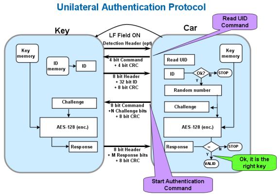
Figure 7 One-way verification
Key Learn: Public / Private
The Key Learn protocol refers to the process of making a car set up a key and sharing it with a key fob. The key can be public or private based on the limitations and security settings of the Key Learn session initiated by the car.
A public Key Learn process typically contains the following (and shown in Figure 8) steps:
1) The car generates a key based on the random number and submits it to the key card
2) The key card "accepts" the key, saves it in memory, and responds (acknowledgment) response
3) After successfully receiving the response of the key fob, the car saves the key in the memory
If the Key Learn protocol cannot block eavesdroppers or protect the car from being used illegally, then a private Key Learn process is required.
Figure 8 Open Key Learn
Two-way or quasi-interactive verification
Quasi-interactive or two-way verification is a more complex verification process. Not exactly interactive verification is implemented in the Atmel anti-theft system because it does not use a random generator at both ends of the system (car and key fob). This implementation uses a Message Authentication Code (MAC) to verify that the car matches the key.
Moreover, in the case of two-way authentication, the authentication protocol is initiated by the car and includes the following (and shown in Figure 9) steps:
1) The unique ID of the car reading key card
2) The car generates a random number query and sends it to the key card
3) The car encrypts the random number and attaches it to the query.
4) The key fob encrypts the challenge (using key 1) and compares it with the received encrypted challenge (MAC)
5) If the results match, the key fob is encrypted (using key 2) and sends a response to the car
6) The car's response to the key fob is compared to its own calculated response (using the same key and query)
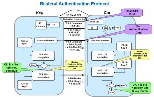
Figure 9 Two-way verification
Encryption layer
The top layer is the encryption layer. This layer contains mathematical functions that convert plain text information into encrypted information. This function should ideally have two characteristics:
1. Uniqueness: For each plain text input, it must correspond to a unique encrypted text output
2. Unpredictability: Plain text to encrypted text pairs must be unpredictable, even if there is a known plain text to encrypted text pair for analysis.
Open and private
Private encryption algorithms have been popular for many years. However, the privacy algorithm has several shortcomings: A) the strength of the algorithm is uncertain; B) the lack of critical code peer-to-peer evaluation mechanism; C) if the algorithm leaks, it may lead to extensive security damage. In recent years, there have been many high-profile examples reported, which are sufficient to illustrate the existence of these shortcomings. A more compelling shortcoming may be the lack of interoperability of the system and the inability to share the same physical and logical layer. This hinders basic market competitiveness and, in many cases, drives up system costs.
To solve these problems, people began to accept the public domain encryption algorithm -- the advanced encryption standard (often called AES). This algorithm originated from the 1997 initiative of the National Institute of Standards and Technology (NIST) to collect public domain encryption algorithms. A total of 15 candidate algorithms were generated that year, and both have undergone critical review in the field of encryption research. This evaluation analysis includes an assessment of the security and efficiency of each algorithm. NIST selected 4 out of 15 candidate algorithms, then entered the second round of public evaluation, and finally selected the AES algorithm in 2000.
As we now know, AES is a symmetric block cipher that uses a 128-bit plain text input and a 128-bit key to produce a 128-bit encrypted output. Because of this symmetry, AES can also operate in reverse, using encrypted output and keys to find and extract raw plain text input.
System security considerations – attacks and countermeasures
There is a common misconception that the security of car alarm systems depends on the strength of the encryption algorithm. Although the strength of the encryption algorithm is important, it does not determine the anti-attack capability of the entire system. Each interface, algorithm, protocol, logic and physical characteristics of the anti-theft system affects the overall security of the system and should be researched and enhanced to improve the anti-aggressiveness of the system.
Algorithm security and countermeasures
As mentioned earlier, encryption algorithms must have unique and unpredictable features. Taking AES as an example, the detailed working principle of the algorithm is completely open to the public. Therefore, it has passed the rigorous evaluation of the research field. This is the best preventive measure so far. So far, scientific research has confirmed the strength of the algorithm and has stood the test of more than 10 years. However, in the case of private algorithms, it is impossible to conduct scientific analysis in the research field, and the strength of these algorithms is completely unknown. In fact, many of these algorithms can't stand the test of time, and their shortcomings have been exposed in recent years.
Protocol security and countermeasures
In systems that use one-way authentication, attacks on the protocol layer are generally "scanned" or "dictionary". In a "scan" attack, the attacker receives a "challenge" from the car and returns a random value as a response. If the protocol contains a 56-bit response, the bit security is 256, ie 256 attempts are required to obtain a correct "question-response" pairing. To prevent this type of attack, consider the following measures:
Increase the bit length of the response to increase complexity
Exponentially exponential growth between successive failure attempts to embed a car
Let the car refuse to try after a certain number of consecutive attempts to fail
In a "dictionary" attack, an attacker collects the correct query (from the attacker) to answer (from the key fob) by directly communicating with the transceiver. These "question-response" pairs are placed in a lookup table or "dictionary" for later reference. Equipped with such a dictionary, the attacker triggers the car to issue a query and then searches the dictionary for the correct response. If the protocol contains 100-bit responses, then 251 attempts are required to obtain a correct challenge-response pair. "Birthday paradox" indicates that the probability of obtaining the correct result is 0.5 after the "question-response" pairing and 2n/2 attempts of 2n/2 records. It can be seen that the overall complexity of this attack is 2n/2+1 = 251. The countermeasures that should be considered in this case are:
Increase the length of the query to increase complexity
Two-way authentication protocol
Physical/logical security and countermeasures
In recent years, the means of attack have become increasingly sophisticated and advanced. "Edge channel" attacks, such as Simple Power Analysis (SPA) and Differential Power Analysis (DPA) and other "intrusive" attacks, have been successfully used to extract the key of a key fob. These so-called side channel attacks measure and evaluate the power consumption of the encryption device, and in combination with the knowledge of plain text cipher text, an additional key can be extracted. The basic theory of these methods is quite complex and beyond the scope of this article. The most powerful measures to defend against these side channel attacks include:
Clock frequency and running randomization
Digital control and encryption work interleaved
"Intrusive" attacks focus on the physical implementation of encryption-related circuits on silicon. As long as the countermeasures are taken into consideration at the beginning of the design process, the implementation of the best defenses is quite simple. Here are some examples of steps you can consider:
Metal shield of the memory block
Non-standard comprehensive library
Grab the position of key digital elements used during encryption
Limit memory access and automatic chip erase if an attempted intrusion occurs
System performance considerations
power consumption
System performance involves different aspects. One is the power consumption of the key fob. This parameter is directly related to the communication distance between the available key fob and the in-vehicle base station. Automakers and leading suppliers often emphasize the importance of coupling factors as a key parameter. However, it describes mainly the mechanical size relationship between the key fob antenna and the in-vehicle base station antenna. This parameter is valid only for a given system configuration and depends on the antenna's inductance, Q factor, drive current, reader sensitivity, and ignition lock core material. In view of this, it is not enough to use this parameter alone to compare the performance of different systems. In fact, in addition to the coupling factor, it is also important to consume power, especially considering that the key card works in a passive battery-free environment, the energy needs to be collected from the magnetic field and stored in a small capacitor, so Power consumption is very limited. By choosing ultra-low-power system components and microcontrollers that can be programmed with equalization software (as much as possible, the microcontroller enters sleep mode), engineers can overcome the aforementioned high coupling factor to compensate for key cards. The high current is a system defect.
Verify response time
Another important factor in the anti-theft system is the time it takes to rotate the key fob inserted into the door lock to the engine. This time should be short enough to make the driver feel no delay. Depending on the mechanical and electrical design of the system, as well as the speed at which a person inserts and turns the key, the time budget should generally be between 300ms and 500ms. A significant portion of this budget is spent on the overhead of the mechanical and body control modules; the remaining 100ms to 200ms is used for the verification process. In terms of speed and security, a good compromise is to use a two-way verification with a query bit length of 100 bits and a response length of 56 bits. In most systems, this will reduce the response time to less than 100ms.
Error handling
To prevent verification from failing for any reason, today's systems require a full verification cycle to restart from scratch and allow up to 3 retries in a given period of time. Atmel's retry strategy is slightly different, it can make the system recover faster from communication errors. All commands and optional data are protected with a Cyclic Redundancy Check (CRC). Both the key fob and the base station utilize the CRC to detect errors and signal these statuses to the respective communication partners, which allows the base station to select the number of repeated messages, the last action, the last response or the last command. This feature enables faster communication recovery and allows more communication recovery attempts in the same amount of time (5-7 retryes, not just 3)
to sum up
By choosing a system component that meets the safety and performance goals of the automotive market and supports a highly configurable open source anti-theft software stack, the task of developing a robust car anti-theft system can be greatly simplified. As a leader in automotive access solutions, Atmel has a complete system solution that includes hardware and software.
The key fob design can be implemented with ATA5580 and ATA5795. Both devices include an LF front end, an AES hardware module that performs fast and efficient cryptographic calculations, and an AVR microcontroller optimized for ultra-low power consumption. They also include programmable flash memory that can be used to run Atmel's open anti-theft protocol or other customer-specific software and to make the anti-theft device completely passive.
The car base station can be implemented with the Atmel ATA5272. The device integrates LF base station functionality and an AVR microcontroller with 8K programmable flash.
In addition to these devices, Atmel also offers users free open anti-theft protocol software that delivers unprecedented user configurability (including many user-selectable features that enable dynamic evaluation of system parameter trade-offs) and Accelerate development and optimization processes:
Logical layer with uplink and downlink baud rate, bit coding and modulation depth
Protocol layer with query and response bit length, one-way or two-way authentication, data field CRC, two keys, private or public Key Learn
AES encryption clock speed "online" from 125 kHz to 4 MHz encryption layer
Taihang Jiaxin lead-acid battery charging system is suitable for maintenance and non-maintenance operations. The primary function of the charging system is to provide continuous load while charging the battery without supervision. It is suitable for high reliability emergency backup power systems. Controlled by solid state thyristors with electronic sensing and monitoring. The charging characteristic is a constant potential with a current limit. The primary function of the charging system is to provide continuous load while charging the battery without supervision. The charger rectifier circuit provides 100% of the rated current, while the float/boost charges a group of lead acid batteries.


Lead Acid Battery Charger,Automatic Battery Charger,Intelligent Rapid Charger,12V Lead Acid Battery Charger
Xinxiang Taihang Jiaxin Electric Tech Co., Ltd , http://www.agvchargers.com