Abstract : This paper first introduces the application of PLC in the flexible manufacturing system, and then describes the composition and control flow of the capping manipulator. From the perspective of PLC control principle, the control flow chart of the pinning robot, the power system diagram, the I/O interface design of the PLC and their address assignment are designed. The experimental verification has achieved the expected control objectives.
This article refers to the address: http://
At present, the Flexible Manufacturing System (FMS) is controlled and managed by the main control computer and related software to process and transport the workpieces, thereby realizing the automated manufacturing of multi-variety variable batch and mixed flow production. The control functions of the industrial flexible manufacturing system are mainly completed by the industrial computer-PLC. The pinning robot of this paper is a unit of the FMS system, which mainly performs the pinning and positioning function of the workpiece.
1 Structure of the pinning unit
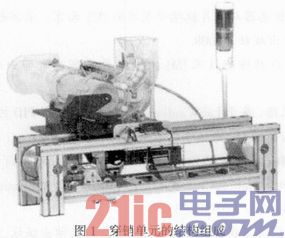
The main function of the pinning unit is to complete the physical connection assembly of the workpiece body and the upper cover by rotating the push pin to push the pin, and the finished workpiece is transported to the lower station with the tray. Its structural composition is shown in Figure 1.
2 pinning robot control flow chart design
The flow chart of the pinning robot control is shown in Figure 2.
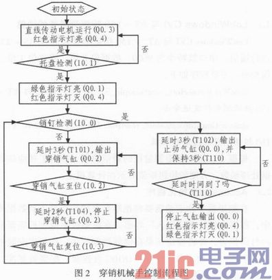
In the figure: 1) Initial state: The linear transmission motor is in the stop state; the pin cylinder is in the home position (ie, the rotary pusher is in the retracted state); the limit lever is erected; the work indicator is off. 2 After the system starts running, the red indicator light of this unit is illuminated; the linear motor drives the conveyor belt to start running and always keeps running state (the special relay that is in the same state as the PLC running/stopping can be used to maintain the running state of the linear transmission motor when the unit is running) 2) During system operation: 1 When the pallet-loaded workpiece reaches the positioning port, the tray sensor sends a detection signal, and after confirming that there is no pin signal, the green indicator light is on, and the red indicator light is off. After 3 seconds of confirmation, the pin cylinder advances to perform the loading pin action. 2 When the pin cylinder sends the in-position detection signal, it will end the propulsion action, and will automatically return after a delay of 2 seconds. After the 3 cylinders are returned to the reset state and the pin detection signal is received, a delay of 3 seconds is performed, and the cylinder is stopped to cause the limit lever to fall to release the tray. (If the pin is installed for empty operation, the pin detection sensor still has no signal after 2 seconds, and the pin cylinder is pushed forward to perform the mounting action until the pin is installed in place). 4 After releasing for 3 seconds, the limit bar is erected, the green indicator light is off, and the red indicator light is on. The system returns to its initial state. After the pin of the station is worn continuously for 3 times, the sensor has not detected the pin penetration, and the alarm is alarmed. At this time, the pin should be added to the lower bin of the pin.
3 pinning robot power supply part design
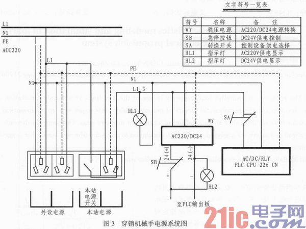
The power supply design diagram of the pinning robot is shown in Figure 3.
4 pinning robot I / O address design
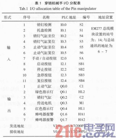
The pinning robot I/O allocation table is shown in Table 1.
5 Conclusion
The control circuit of the PLC of the pinning robot designed in this paper has high reliability and strong anti-interference ability. It has been verified by experiments that the actual control requirements have been fully met, and its control method is worthy of widespread promotion and application.
Fiber Optic Patch Panel,Fiber Patch Panel,Fiber Distribution Panel,Optical Patch Panel
Cixi Dani Plastic Products Co.,Ltd , https://www.danifiberoptic.com