Design of a car infrared night vision device based on PIC microcontroller
0 Preface
With the rapid development of the automotive market and the increasing security awareness, people have higher and higher requirements for automotive safety and security technology, and the existing automotive lighting systems have a line of sight under low visibility conditions such as snow nights, snow days or heavy fog. The shortcomings of not far away and poor effect have become one of the hidden safety hazards of automobile driving. What's more serious is that when driving at night, the driver is usually disturbed by the lights of the other vehicle to appear a blind spot, which is prone to accidents. The night vision system can help the driver navigate in the dark, so that the driver can see the driving environment clearly in both light and darkness. Therefore, the development of a car infrared night vision system with simple structure, stable performance, good reliability and strong applicability has important market application prospects.
1 Overall system design
1) System principle
According to different working principles, infrared night vision systems are divided into passive infrared night vision systems and active infrared night vision systems. The active infrared night vision system uses its infrared light source to irradiate the target actively, the infrared lens reflected by the target is received by the objective lens of the optical system, and an infrared image of the target radiation is formed on the photocathode surface of the infrared image converter. The kinescope performs spectral conversion and brightness enhancement on the infrared image of the target, and finally displays the visible light image of the target on the fluorescent screen. The human eye can observe the enhanced target image through the eyepiece. Considering the durability of use, economic rationality, versatility of devices, etc., most active infrared night vision systems are selected as vehicle-mounted systems.
According to the functional objectives and design requirements, this system is mainly composed of infrared illumination lamp, CCD camera, video processing system and car display.
2) Hardware design
(1) Camera selection
The camera is also called camera or CCD. It can convert light into electric charge and store and transfer the electric charge. It can also take out the stored electric charge to change the voltage. It is an ideal imaging element. Its working principle is: the light reflected by the camera body, propagates to the lens, and focuses on the CCD chip through the lens. The CCD accumulates the corresponding charge according to the intensity of the light, and periodically discharges to generate an electrical signal that represents a picture. Filtering and amplification processing, output a standard composite video signal through the output terminal of the camera. Here select the WAT-902H2 camera as the camera. It has the advantages of good camera effect, easy maintenance and economical benefits.
(2) Design of infrared irradiation part
Use far-infrared laser as the light emitter. It is a laser transmitter with good monochromaticity, concentrated beam, small size, long life and high electro-optical conversion efficiency. It is composed of fiber-coupled semiconductor laser, drive circuit, temperature control circuit and beam shaping lens. The core part is the drive circuit design. DD312 is selected as the driving chip. It is a single-channel constant current driver chip designed for high-power LEDs. It is a current-sucking architecture that can provide a constant current output of up to 1A. It also supports the enable switch function. The command signal is applied to the enable terminal of DD312 through the optocoupler to control the switch of the laser. The driving circuit is shown in Figure 1.
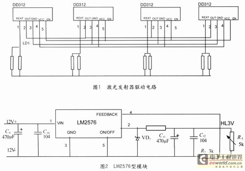
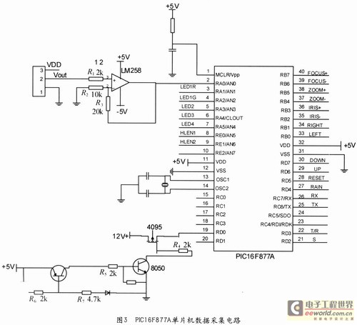
(3) Power module design
The display, MCU, MAX487 communication chip, CCD camera, and laser emitter drive circuit in the system all require power supply. Among them, the single chip microcomputer and DD312 driver chip require that the power supply voltage is relatively stable, the ripple is small, and the electromagnetic interference is small. The LM2576 module is used to provide a regulated power supply for the microcontroller and the DD312 driver chip (Figure 2). The working voltage of the MAX4877 chip is relatively high and the range is relatively wide. The NW1-05S05S power conversion module is used to provide power for it.
(4) Design of control system
Using PIC16F877A, PIC16F876A two kinds of single chip microcomputer as the control chip of the system, the entire control system is a small transmission system. Among them PIC16F877A one-chip computer is regarded as the initial end of the transmission system, responsible for data collection and "memory" button; Max487 chip is a communication chip, responsible for receiving and transmitting signals. PIC 16F876A single-chip microcomputer is used as the receiving end of the transmission system to control the rotation of the motor.
â‘ Beginning
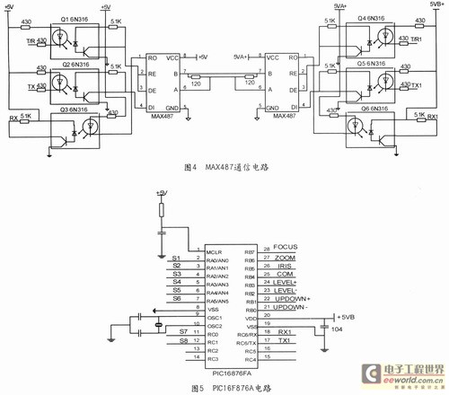
The core of this part is the PIC16F877A microcontroller. It is an 8-bit single-chip microcomputer produced by the American Microchip company, with a unique RISC structure, a Harvard bus structure with a separate data bus and command bus. It connects each terminal device, responds to the query command sent by the host computer, and sends back the status information of the device under test to the host computer. The I / O port of the single-chip microcomputer is connected to the terminal of the device under test to obtain the required state information. The circuit is divided into three parts: data acquisition circuit (Figure 3), LED display circuit, button circuit.
The external temperature sensor of pin 2 of the single-chip microcomputer is used to transmit the real-time temperature change signal of the system to the single-chip microcomputer; the LED display circuit of pins 3-7 is connected. When the low-level signal of the pin is turned on, the corresponding LED turns on; the external laser drive circuit of pins 8 and 9 , Detect the laser state; 19 feet external semiconductor cooler, collect information, and decide whether to trigger the semiconductor cooler work; 22, 25, 26 feet connected to the communication circuit, to transmit signals to the main control chip; 27 ~ 40 feet for PTZ And the lens key detection signal, when the operator presses the key on the panel, the single-chip microcomputer receives the key signal through these ports, and sends this information to the main control chip through the communication circuit. After receiving the signal, the main control chip analyzes, controls, and executes The corresponding command.
â‘¡Communication circuit
The communication circuit connects the initial end and the receiving end of the transmission system, and the main function is to realize the reception and transmission of signals. Using Max487 chip, it is a low-power half-duplex transceiver device for communication, which integrates a driver and receiver. The initial end first encodes the signal, the receiving end decodes the signal, and in order to eliminate interference, the circuit is isolated using an optocoupler. See Figure 4.
â‘¢End
The terminal control chip adopts PIC 16F876A microcontroller. The pins RA0-RA5, RC0, and RC1 are the eight signal input ports for detecting PTZ up, down, left, right, up reset, down reset, left reset, and right reset; RB0-RB7 are the control lens The eight ports of focal length, magnification, and rotation of the gimbal up and down, left and right, and an external relay circuit control the rotation of the motor. As shown in Figure 5.
3) Software design
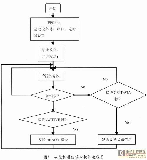
The entire system software is divided into the PIC 16F876A end of the master control machine and the PIC16F877A end of the slave control machine. In addition to the software of the communication interface, the software of the host computer also includes the user interface and data processing. The slave computer software includes data acquisition and MAX487 communication program. The software flow of the communication interface of the slave computer is shown in Figure 6.
2 Experimental results
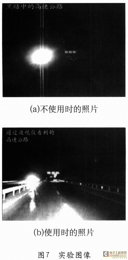
Figure 7 is a picture taken on the highway. Where a is the picture when the night vision system is not used, and b is the picture when the night vision system is used. Experimental results show that this system can enable drivers to accurately identify the road ahead in the dark and reduce traffic accidents.
3 Conclusion
This article uses the PIC microcontroller to design a complete set of infrared night vision system, which has the advantages of simple structure and high reliability. Especially suitable for long-distance bus driving, which can effectively reduce traffic accidents and has very good social benefits.
Dk Phase Motor Centrifugal Pump,A2 Phase Motor.Driver,Split Phase Motor A2,Motor Control Board
Ningbo Zhenhai Rongda Electrical Appliance Co., Ltd. , https://www.centrifugalswitch.com