Power is often an essential part of the electronics design process, and many devices (especially those that use batteries) are powered by DC-DC. These power supplies typically have three topologies, known as buck, boost, and buck-boost (also known as inverTIng), which are used for buck, boost, and reverse, respectively. However, there are times when the output voltage and input voltage we need are close to or within the input voltage range. At this time, the above three structures alone cannot meet the requirements. In this regard, some people use the method of first drop or rise first or then rise, then this will greatly reduce efficiency; some companies have developed chips that automatically switch the boost buck mode, but this is very expensive. Is there an efficient and cheap way to achieve our goals? Of course, this is the SEPIC topology.
The basic structure of the SEPIC circuit is shown below:
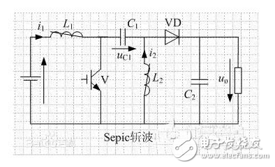
This circuit requires 2 inductors. When the switch is turned on, it charges L1 and L2 (via C1), and the load is supplied by the output capacitor C2. When the switch is turned off, the current of L1 is output to the output capacitor C2 through C1 and the diode, and the current of L2 is also output through the diode. Go to C2; change the output voltage by changing the on-time of the switch. The output voltage of the circuit can be greater than, less than or equal to the input voltage, and the intermediate capacitor C1 can also provide isolation when the power supply is not needed.
Here is a circuit diagram that I have used:
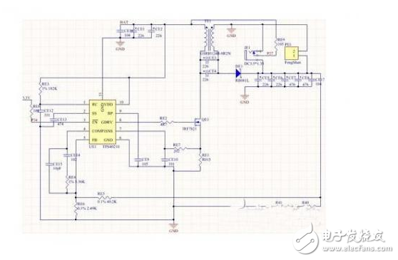
This circuit stabilizes the input voltage (9-12.6V) of the three-string lithium battery at 12V, using TI's TPS40210 chip, which can be used not only for BOOST circuits, but also for SEPIC circuits. The inductor used here is a common-mode inductor. Since the voltage and current of the 2 inductors in the SEPIC circuit are completely identical, a common-mode inductor can be used instead of two inductors, which not only reduces the cost, but also requires only mutual inductance. Half the inductance is enough.
There are many usages of the SEPIC circuit, and there is not much to describe here. In short, the structure is a structure with many advantages, but the research is relatively small, the data is relatively small, and the use of the system requires everyone to work together. However, this circuit also has a fatal flaw.
Since the capacitor in the middle is used as the energy storage component, the power of the circuit cannot be made large, and the performance of the circuit has a great relationship with the capacitance in the middle. Therefore, in the actual use process, try to choose a capacitor with low ESR and high rated current.
Villa Lift,Attic Elevator,Small Lift For Home,Electric Lifts For Homes
XI'AN TYPICAL ELEVATOR CO., LTD , https://www.chinaxiantypical.com