As everyone knows, the performance level of green LEDs does not reach the same red and blue LED. However, black spots can be reduced by reducing current density, using a larger chip, and optimizing growth conditions, and can minimize the distance between LEDs of 190 lm/W at 100 mA drive current. Osram's AndreasL? Ffler and Michael Binder said.
The biggest flaw in LED bulbs is second only to the price that is not ideal. This shortcoming is produced by the process of making white LEDs: the GaN-based blue chip excites the yellow phosphor, mixing the two colors to produce white light. In this way, the red region of the visible spectrum does not contribute much to the light output.
A more advanced method of making white LED lighting products - also a method of solid-state projection display - that is, LEDs made of red, green, and blue, mixed to produce white light. The advantage of this method is that it is not limited to a higher color rendering index, but also achieves higher light efficiency and flexible control of color.
To produce an energy-efficient system in a mixed color, a high-efficiency light source must be used. The performance of blue and red LEDs has been significant, and recent technological improvements have led to peak power conversion efficiencies exceeding 81% and 70%, but the performance of green LEDs is far behind. The phenomenon that such GaN-based LEDs are not highly effective is called a "green light gap."
Green wavelength band
Increasing the efficiency of green LEDs is a major challenge because of the inability to take advantage of the ideal maturity of materials systems. The III-N series used to create high-efficiency blue LEDs will be less efficient at longer wavelengths, while the more efficient Group III phosphides in the red range will face the same distress; The light emitted by the LED emits shorter wavelengths and the efficiency is reduced. In short, the material system is inefficient in the yellow-green spectrum.
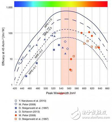
Figure 1: Luminous efficiency of Group III nitrides (green data points) and Group III phosphide LEDs (red light data points) at different wavelengths. The blue line represents the corresponding value of the photometric function of the International Commission on Illumination (CIE) in 1924 multiplied by the electro-optical conversion efficiency (WPE). The yellow-green range is marked with a yellow color and is neither sufficiently covered by the Group II nitride nor by the Group III phosphide. This is the essence of the green gap problem.
For Group III phosphides, emitting light to the green band becomes a fundamental barrier to the material system. Changing the composition of AlInGaP makes it glow green instead of red, orange or yellow—causing insufficient carrier confinement due to the relatively low energy gap of the material system, eliminating effective radiative recombination.
In contrast, Group III nitrides are more difficult to achieve, but the difficulty is not insurmountable. With this system, two factors that cause the efficiency to decrease due to the extension of light into the green band are: external quantum efficiency and electrical efficiency degradation.
The decrease in external quantum efficiency is due to the high forward voltage required for green LEDs. These devices have a very high internal voltage field. Therefore, at a given voltage, the voltage applied to such LEDs will be higher despite the lower bandgap. A higher drive voltage causes the power conversion rate to drop. The second disadvantage is that the green LED decreases as the injection current density increases, which is trapped by the droop effect. The Droop effect also appears in blue LEDs, but the effect is even greater in green LEDs, resulting in lower operating currents.
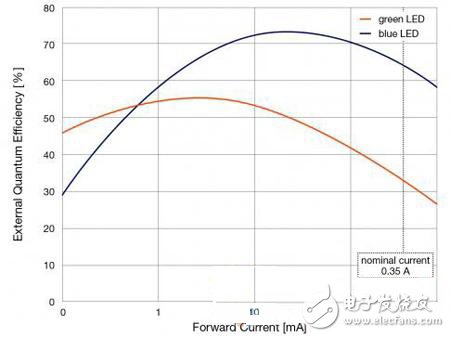
(Fig. 2) Comparison of external quantum efficiency between 1mm2 blue InGaN and green GaN at wavelengths of 442nm and 530nm
The cause of the droop effect has caused intense discussion in the nitride industry. Because the loss rate of the droop effect is cubic dependent on the charge carrier density under electroluminescence and photoluminescence stimulation, most of the guesses point to the Auger recombination as the cause of the droop effect.
However, there are many speculations about the causes of the droop effect, not just the Auger compound, which includes misplacement, carrier overflow or electron leakage. The latter is enhanced by a high voltage internal electric field.
110KV-220kv Oil Immersed Transformer
110Kv-220Kv Oil Immersed Transformer,Anti - Interference 110Kv Transformer,Low Loss 110Kv Oil-Immersed Transformer,High Load Capacity 110Kv Oil-Immersed Transformer
Tianhong Electric Power Technology Co., Ltd , https://www.tianhongtransformer.com