When buying a digital storage oscilloscope (DSO), people tend to focus on bandwidth, sample rate, memory depth, and channel count, but one performance is often overlooked. This is the oscilloscope's waveform capture rate. The waveform capture rate, also known as the waveform refresh rate, is one of the important parameters of the oscilloscope.
Before we understand the waveform capture rate, we first need to understand the structure of the digital oscilloscope:
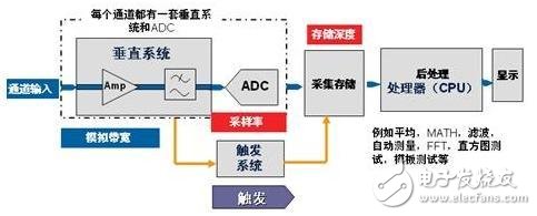
Figure 1: Block diagram of a traditional digital oscilloscope.
In the traditional digital storage oscilloscope, the waveform data processing and display are all completed in the CPU, and the CPU becomes the bottleneck of the entire data acquisition, processing and display. A large period of time is required between every two frames, waiting for the CPU to complete the processing of the previous frame, in order to start the acquisition of the next frame. Referring to Figure 2, the time between two acquisition frames is called the dead time of the oscilloscope acquisition. Traditional digital storage oscilloscopes have long dead time, and occasional glitch signals can easily fall into the dead zone, which is difficult to collect by the oscilloscope.

figure 2
The dead time may account for more than 99% of the time of the signal stream. One way to reduce dead time is to increase the refresh rate.
The SIGLENT SDS2000 oscilloscope adopts Siglent's innovative waveform acquisition and image processing engine, which uses FPGA group to complete waveform processing and display, which greatly shortens the dead time between two frames.
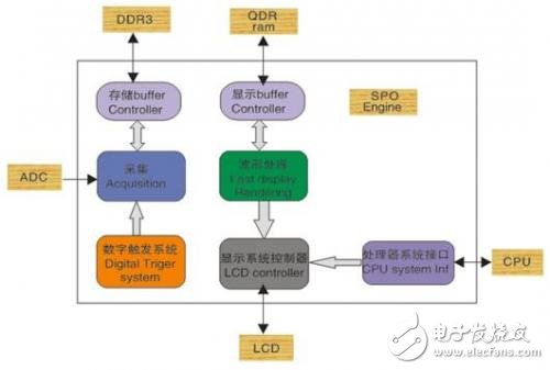
Figure 3: Block diagram of the SIGLENT SDS2000 oscilloscope (SPO Engine is a waveform acquisition and graphics processing engine independently developed by Dingyang)
Many engineers may encounter such a situation during hardware debugging: in the later stage of debugging, the welding of the main components of the board is basically completed. During the function verification process, it is found that the system will fail after running for a short time, but Through the oscilloscope to view the key clock and enable signal are "no problem", the fault is finally determined as the cause of the software, and then the code is checked line by line for software optimization. Now that the oscilloscope's dead time has been clearly understood, there is a possibility that the oscilloscope misses the sporadic signal that causes the system to malfunction. The figure below can clearly illustrate this problem.
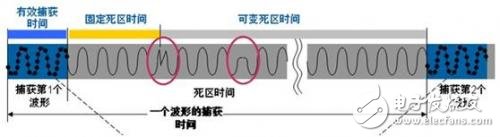
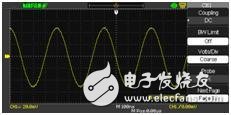

Figure 3: The traditional oscilloscope has a long dead time, low waveform capture rate, and it is difficult to capture sporadic glitch/abnormal signals.
Usually, the easiest and most intuitive way is to see if there is an abnormal signal by triggering the signal edge and using the "afterglow display" method.
The figure below shows a normal pulse signal, but an abnormal signal appears every tens of thousands of cycles. We hope to capture the sporadic signal using the “afterglow display†method of the traditional oscilloscope.

Figure 4: "The afterglow display" mode
This way looks good. However, do all the waveforms that have ever appeared, including the anomaly signal, be displayed on the screen? no! The "afterglow display" mode only continuously accumulates waveforms that have appeared in history, but the anomaly signals that occur during the time interval between the two acquisitions of the oscilloscope (ie, dead time) cannot be found by persistence.
On the platform of the SDS2000 series super-fluorescence oscilloscope, the 50ns time base can achieve a waveform capture rate of 110,000 frames per second. Compared with the traditional oscilloscope 50ns time base, it can only achieve a waveform capture rate of about 200 frames per second. The SDS2000 oscilloscope with SPO engine can quickly capture sporadic glitch and abnormal signals.
The figure below is due to the high capture rate of the SDS2000 oscilloscope, which makes it easy to capture and observe this sporadic anomaly.
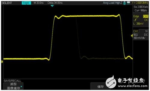
Figure 5: The dead time is short, the waveform capture rate is high, and the occasional glitch/abnormal signal is quickly captured;
Medium Rate Nicd Battery KPM Series
Established in 1956, during the China first five-year-plan, Henan Xintaihang Power Source Co., Ltd. (Factory No.755) was the first R&D and manufacturing enterprise in China in the field of alkaline storage batteries and modular power system and it was also the military factory which owned the most varieties rechargeable batteries in domestic. Taihang was located in national Chemistry and Physicals Power Source Industrial Park, Xinxiang City, Henan, China.
Medium Dishcharge Rate Nickel Cadmium Battery, KPM10~KPM1000, 0.5C ≤Max. discharge current <3.5C
The nickel–cadmium battery (NiCd battery or NiCad battery) is a type of rechargeable battery using nickel oxide hydroxide and metallic cadmium as electrodes. The abbreviation NiCd is derived from the chemical symbols of nickel (Ni) and cadmium (Cd).
Ni Cd Rechargeable Battery,Kpm500Ah Battery,Medium Discharge Rate Nickel Battery,Nickel Cadmium Battery For Ups
Henan Xintaihang Power Source Co.,Ltd , https://www.taihangbattery.com