Although there are many different in-vehicle networking standards and automotive OEMs have many different requirements for EMC, this article focuses on a topic that has proven to be particularly challenging: a controller LAN (CAN) Radio frequency (RF) emissions from the bus.
CAN uses balanced differential signaling to transmit baud rates up to 1 Mbps (or higher, provided that the "Flexible Data Rate" variable is used). Ideally, the use of differential signaling avoids all external noise coupling. Since each half-difference pair (called CANH and CANL) is symmetrical when changing, the interference caused by their noise is destructive. However, no CAN transceiver is perfectly ideal, and the low value asymmetry between the CANH and CANL signals produces a differential signal that is not fully equalized. When this happens, the common mode component of the CAN signal (the average of CANH and CANL) will no longer be a constant DC value. Instead, it will exhibit noise associated with the data.
Two major types of imbalances can cause this noise. One of them is the mismatch between the steady state common mode voltage levels during the dominant (driven) and recessive (high impedance) states.
This steady state mismatch will result in a noise pattern similar to the scaled version of the CAN data itself. This noise pattern is broad in its spectrum and appears as a series of discrete spectral lines that extend to very low frequencies and are evenly spaced. A timing mismatch can result in a noise pattern consisting of short pulses or interference that appears as long as there is an edge transition in the data. The spectral content of this noise pattern tends to concentrate on higher frequencies.
The waveform in Figure 1 shows a common mode noise that can be observed on the output of a typical CAN transceiver. In this image, the black trace (channel 1) shows CANH, the purple trace (channel 2) shows CANL, and the green trace (data function) is the sum of CANH and CANL. This summation process gives a waveform whose value is equal to 2 times the common mode voltage at a specified point at this time.
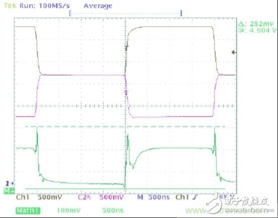
Figure 1: Typical CAN Transceiver CANH/CANL Output and Common Mode Noise
Common mode waveforms show two types of noise: high frequency noise corresponding to dominant to recessive/recessive to dominant transitions, while low frequency noise corresponds to dominant and recessive common modes that do not match.
Since the common mode portion of the signal can be coupled to other components in the system (or to the external system) (through radiation or conduction paths), this common mode noise directly affects the radioactivity. Conducted emissions from this device are measured in accordance with Industrial Engineering/Electronics (IBEE) Zwickau's engineering services; as shown in Figure 2, the device's conducted emissions are combined with an ordinary automotive original equipment manufacturer (OEM) limit line. Draw together.
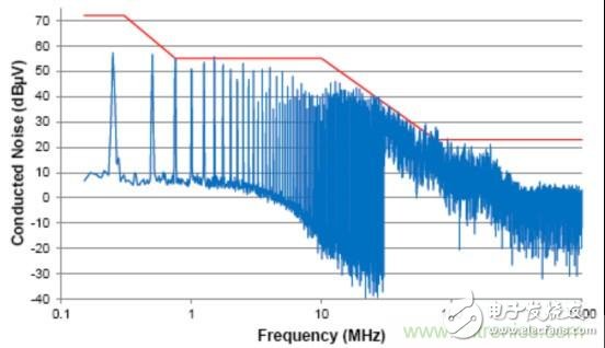
Figure 2: Conducted emissions from a typical CAN transceiver
The output of this transceiver radiates beyond the OEM requirements in the low and high frequency regions. In order to reduce the radiation to a satisfactory level, some external filtering must be used.
The most common filter component in the CAN bus is the common mode choke (shown in Figure 3). The common mode choke is constructed by winding two coils on the same core. In terms of the arrangement of the direction of each coil winding, the common mode current (that is, the direction of the current in each coil is uniform) has a magnetic flux sharing the same polarity. This allows the common mode choke to operate as an inductor for the common mode signal, providing an increased impedance with increasing frequency. Conversely, differential mode currents (that is, opposite current directions within each coil) will cause their magnetic flux to interact with the reverse polarity. For an equalized waveform such as a CAN signal, the magnitude of the opposite magnetic flux in each coil will be equal, so no static flux will accumulate in the core. This allows the choke to operate as a short circuit for the CAN signal.
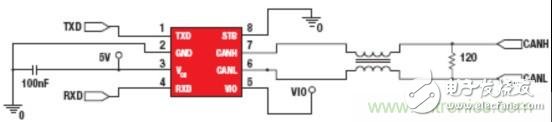
Figure 3: Schematic diagram of the common mode choke circuit
This technology is very effective in reducing CAN bus emissions. For example, when a 51μH common mode choke is used to retest a device that does not meet the emission requirements, performance is greatly improved (Figure 4).
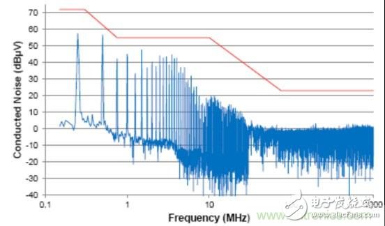
Figure 4: Conducted emissions from a typical CAN transceiver with a common mode choke
However, there are some disadvantages when adding a common mode choke. A significant disadvantage when using common mode chokes is the extra space required on the printed circuit board and the extra bill of materials cost. However, in addition to this, some minor effects on the CAN bus should be considered. Since the choke coil introduces some series inductance, this inductor generates resonance when combined with the parasitic capacitance of the CAN network. Although common mode noise is reduced in most frequency bands, these resonances cause an increase in the amount of noise at the resonant frequency. This effect can be observed in the common mode noise waveform shown in FIG.
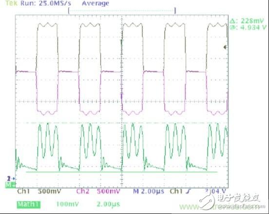
Figure 5: Common mode noise caused by choke inductance
This narrowband noise is particularly difficult to manage. It is often very strong and, due to variations in choke inductance and bus capacitance, its frequency will vary from system to system. It should be noted that the inductance of a common mode choke is usually specified over a wide tolerance range (eg -30% to 50% of the nominal value). Similarly, the bus capacitance of a CAN network will vary depending on the type and length of cable connections used, the number of nodes in the network, and the design of each node. Another unexpected result of the common mode choke is the increased transient voltage risk on the bus. Fault conditions such as shorts to the power supply, battery voltage, or system ground can cause sudden changes in common mode current. This occurs when the short-circuit is connected/disconnected and the CAN drive transitions between dominant and recessive states. When the current flowing through the choke inductor changes rapidly, a large voltage potential is generated at the CAN terminal of the driver IC. In some cases, this voltage may exceed the transient overvoltage handling capability of the CAN device and can cause permanent damage.
To reduce emissions while avoiding the adverse effects associated with common mode chokes, an alternative solution can be used: reducing the common mode noise output of the CAN driver. This may seem simple and straightforward, but it requires careful and serious design by semiconductor manufacturers. The CANH and CANL voltage levels during recessive and dominant states need to be tightly controlled to ensure that the CAN bus waveforms are as balanced as possible.
Furthermore, when CANH and CANL lines are switched between dominant and recessive states, the transition time and timing offset between them need to be well matched to limit common mode noise present in the high frequency band.
The transient waveform for the TI TCAN1042-Q1 CAN transceiver is shown in Figure 6. The corresponding radiation profile is given in Figure 7.
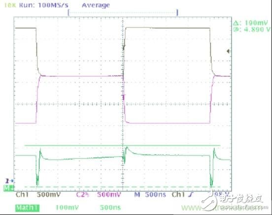
Figure 6: CANH/CANL Output and Common Mode Noise
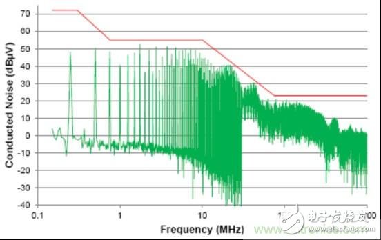
Figure 7: Conducted emissions from a car fault protection CAN transceiver
The well-matched output stage of the TCAN1042-Q1 makes the output common-mode noise extremely low. This allows radioactivity to meet OEM requirements without the use of external common mode filter components such as chokes.
in conclusion
Although the common mode choke is a method to alleviate the EMC problem of the CAN bus, it is widely used in the automotive industry, and the new high-performance transceiver is making the common mode choke become dispensable. Without the common mode choke, the CAN bus can be implemented smaller and at a lower cost while avoiding problems such as circuit resonance and inductor voltage spikes.
Lv Power Cable,Aluminium Steel Tape Armor Cable,Xlpe Sta Cable,Steel Tape Armor Xlpe Cable
Baosheng Science&Technology Innovation Co.,Ltd , https://www.bscables.com